Skewed Motor option
Introduction
Skewed Motor is an option dedicated to the analysis of rotating electric machines with skewing, allowing a straightforward geometric and physical description in 2D and the consideration of continuous or step skewing effects.
The Skewed Motor option is available when a solution is created.
This option is available for:
- 2D Transient Magnetic solution
Introduction : skewing in rotating electric machinery
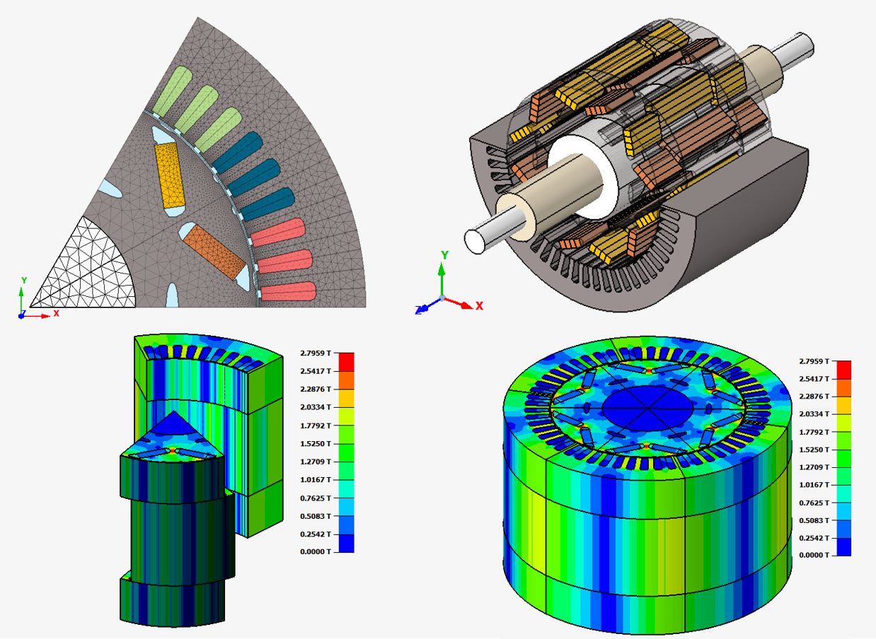
Skewing is a design technique that corresponds to continuously “twisting” or slanting the geometry of the slots of the magnetic circuit of a rotating electric machine away from its axial direction. Skewing is usually performed in the rotor, but the stator slots of a machine may also be skewed in certain designs. Figure 1 shows the example of an induction machine rotor with skewed slots.

Skewing corresponds to spreading the current-carrying conductors housed in the machine slots along a certain angle through the machine’s axial length. Consequently, it may be regarded as a special form of winding distribution that may be applied to either squirrel cage bars in induction machines or to regular stranded windings in other types of machines.
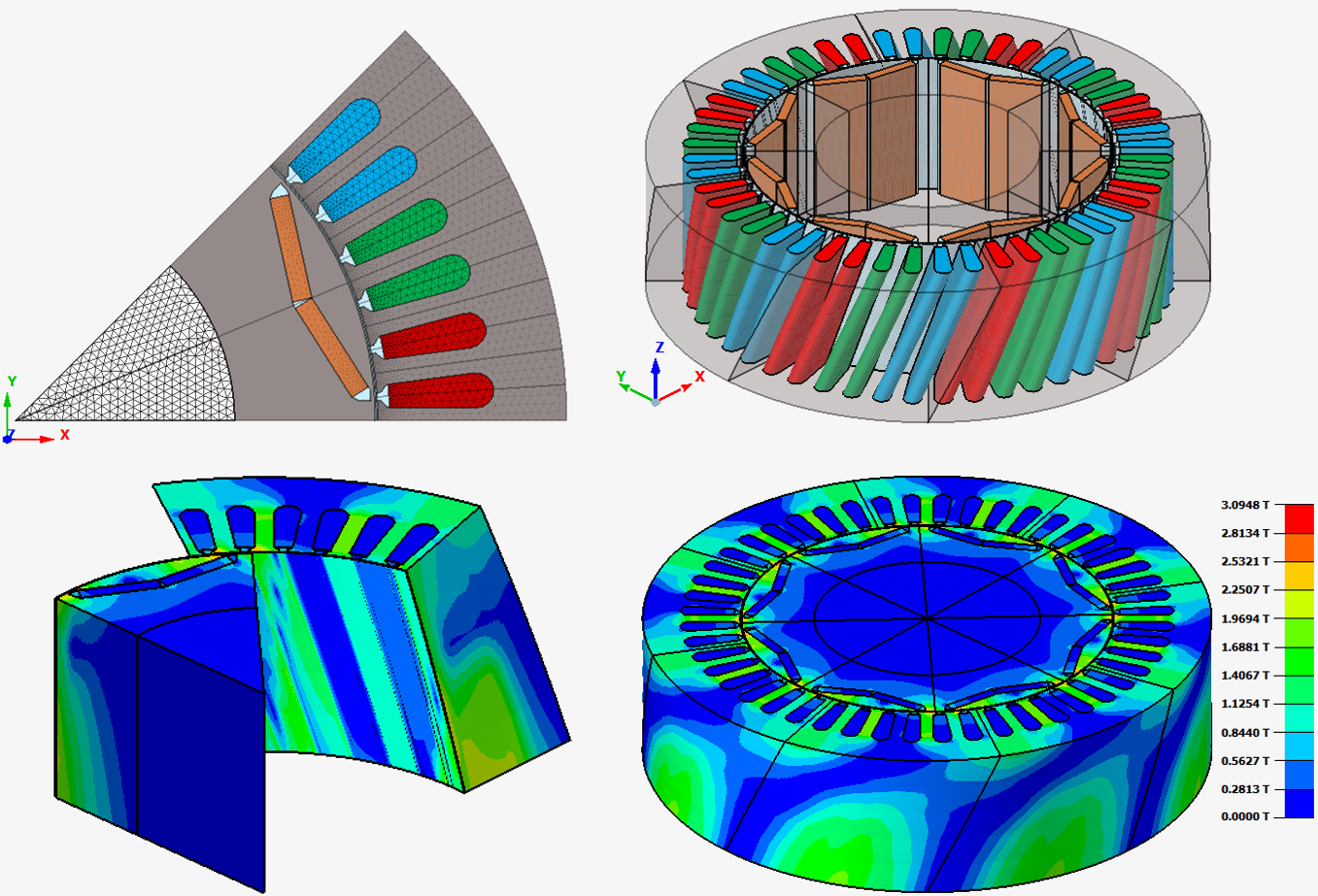
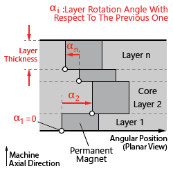
In the more specific context of the permanent magnet machine design, a related design technique known as step-skewing is also commonly employed. It corresponds to modifying the angular position of the permanent magnets along the axial direction of the machine in discrete steps, as shown in Figure 2.

- a reduced cogging torque,
- diminished vibration and noise and
- reduced harmonic distortion in the induced electromotive forces of its windings
What is the Skewed Motor option?
Accordingly with the discussion above, the cross-section of a skewed electric machine changes slightly along its axial length. Consequently, this class of machine cannot be properly represented in a simple 2D SimLab database. On the other hand, representing a machine in a 3D SimLab database may be laborious or time consuming, and the resulting project may require additional computer resources to be solved.
- The Skewed Motor definition is a possible option of the 2D Domain solution. Its like a 2D description during the pre-processing stages, allowing a straightforward description of the geometry and physics of the electric machine in two dimensions, based only on one of its cross-sections
- After solving, and while in post-processing, allowing the exploitation of physical quantities in a three-dimensional representation of the skewed machine like a 3D SimLab database
- The transition from a 2D description of the machine to the 3D analysis of the results is possible due to the specialized physical applications provided by the Skewed Motor option, which consider the effects arising from the skewing
| Example of a Step Skew model in SimLab |
|---|
 |
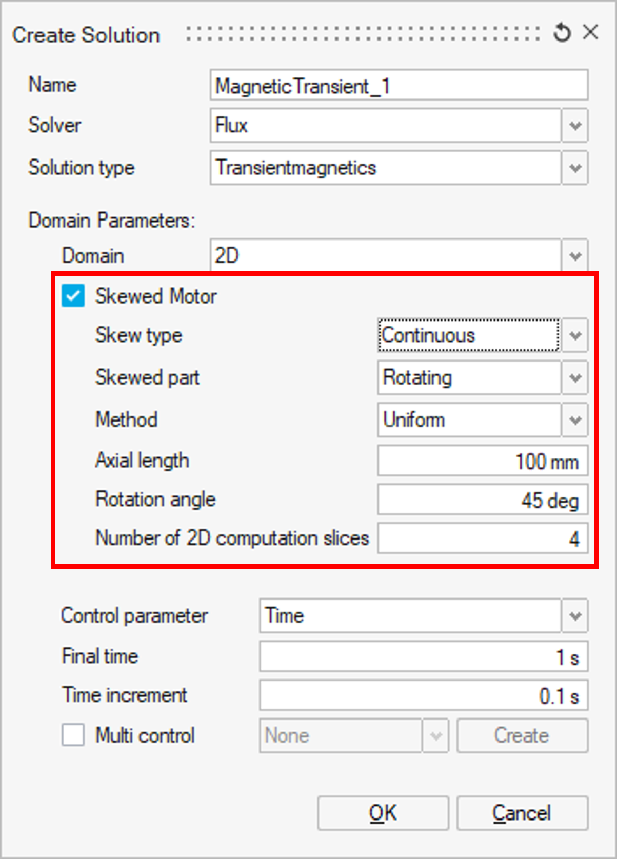
| Example of a Continuous Skew model in SimLab |
|---|
 |
More specifically, during the creation of a 2D solution with skewed Motor option, additional geometric information related to the skewing are asked. This complementary data allows to solve a series of 2D finite element problems, each one associated to a "slice" of the skewed machine along its axial length. Then, a 3D representation of the machine is built and these linked 2D problems are solved.
The Skewed Motor option is a powerful tool for the design and analysis of machines with improved performance due to skewing, and may be efficiently employed together with its native data export tools and other Altair solvers in the context of NVH (noise, vibration and harshness) applications.
Dialog box
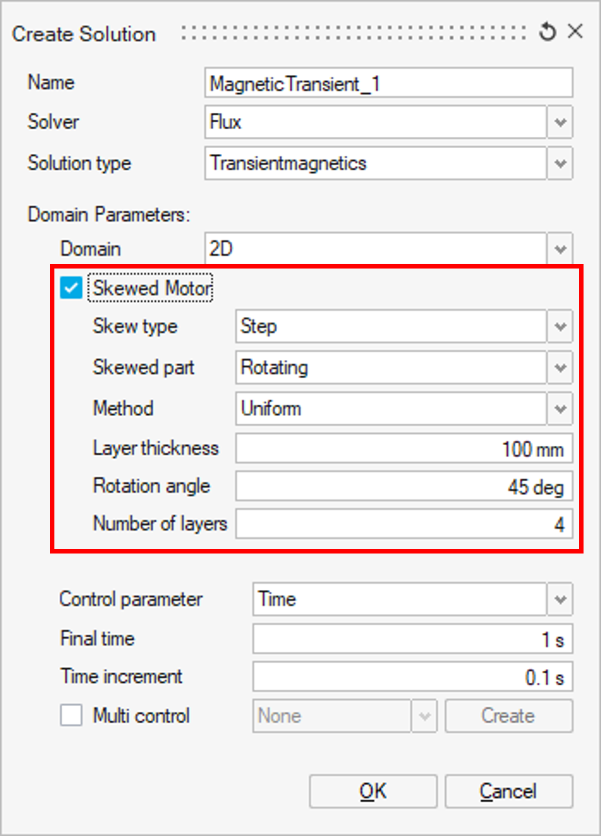
The parameters of the Skewed Motor option depending to the Skew Type.
| dialog box | |
|---|---|
| Continuous Skew type | Step Skew type |
 |
 |
 |
 |
Skew type
Both types of skewing are available for the 2D magnetic solutions:
Skewed parts
The user should choice a motion for the skewed parts between:
- Rotating
- Fixed
- If the Fixedskewed part was chosen, no need to create the corresponding motion, the stator of the machine will be consider fixed (i.e., a machine with a skewed stator is being described).
- On the other hand, if the Rotatingskewed part was chosen, a motion with Rotating around one axis should be created and assigned to the bodies representing the skewed rotor of the machine (i.e., a machine with a skewed rotor is being described).
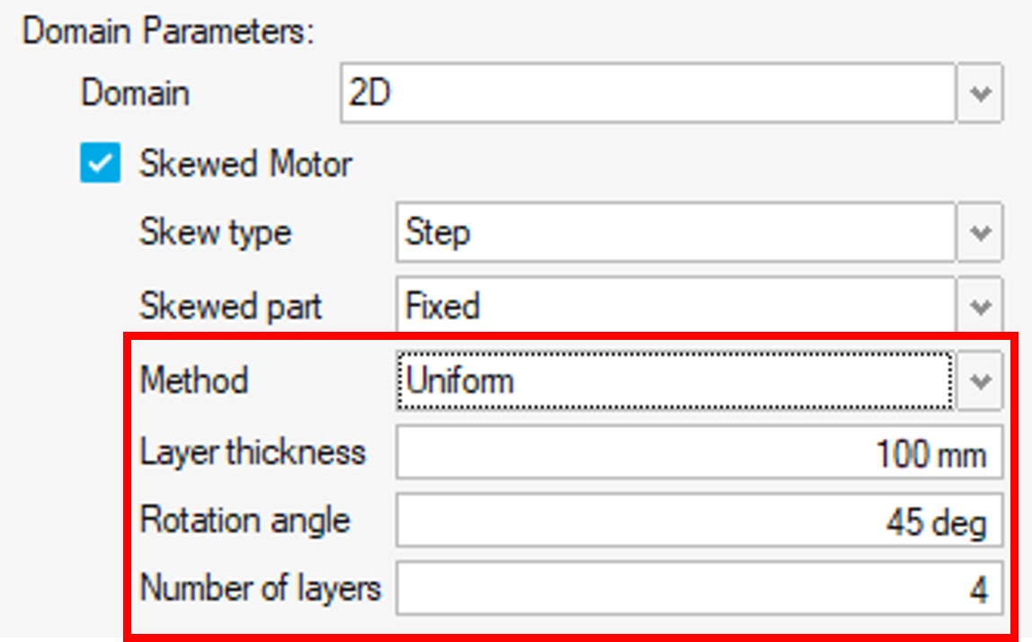
Method
There two possibilities to define the skewed parameters:
- Uniform method: the user should define the parameters identical for all
layers:
- the layer thickness
- the rotation angle
- the number of layers
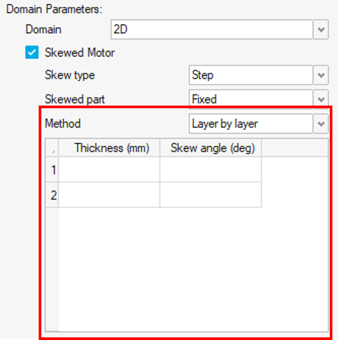
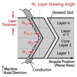
- Layer by Layer method is also available and allows the
description of more complex topologies (V, W or zig-zag skewing, for instance).
In this approach, the user must fill a table in which each line represents a
skewed layer. Two parameters are required for each layer:
- the Thickness of the layer
- the Skew angle (in degrees)Note: For a Step Skew type, the skew angle must respect to the previous one
| Uniform | Layer by Layer | |
|---|---|---|
| Continuous Skew | 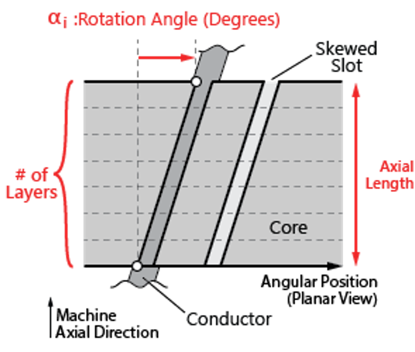 |
 |
| Step Skew | 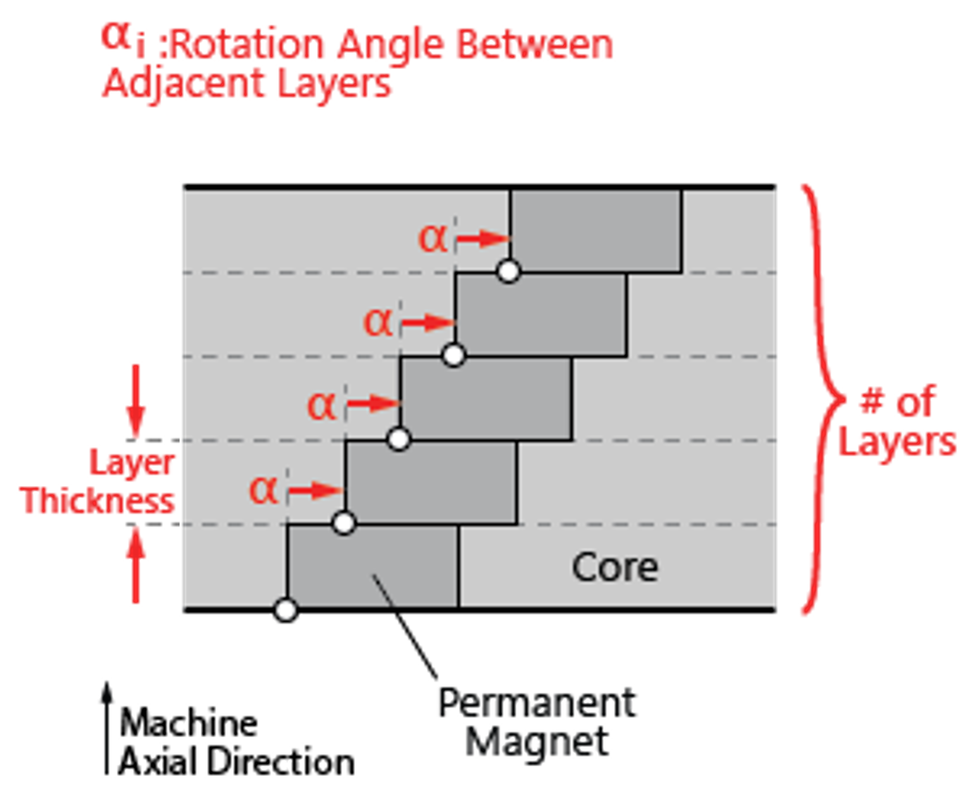 |
 |