Coils modeling
Foreword: physical aspects
A coil is a two-terminal circuit component formed from a conductor wound to a certain number of turns on a supporting structure. The coil support may be composed of either a magnetic or a non-magnetic core, and most frequently, the conductors employed are single-stranded or multi-stranded wires. Coils may also be constructed by winding conductors with non-circular cross-sections and even metallic sheets or any other shape.
When a power supply is connected to the terminals of a coil, an electrical current traverses the winding and generates a magnetic flux density field in the surrounding media. The resulting field is governed by the Biot-Savart law and stores magnetic energy drawn from the supply. On the other hand, if a time-varying magnetic flux links the coil turns, an electromotive force is induced between its terminals as predicted by Faraday and Lenz laws.
Other secondary physical phenomena also take place, depending on materials and on the time rate of change of the current flowing in the coil. These include Joule losses, which may be augmented by an uneven current density distribution arising from skin and proximity effects at higher frequencies. Coils also tend to resonate at sufficiently high frequencies due to parasitic inter-turn capacitive effects.
The coils in SimLab
- Meshed or non-meshed coils
- Easy representation multi-stranded coil or solid conductor
The two categorizations will be explained in next paragraphs.
Here is a table showing the categorization of the SimLab coils features:
| Multi-stranded coil | Solid conductor | |
|---|---|---|
| Meshed coil | Imposed Current Coil LBC | Passive Solid Conductor LBC |
| Coil component in the circuit | Solid Conductor component in the circuit | |
| Non-Meshed coil (3D) | Non-Meshed Coil LBC (3D) | - |
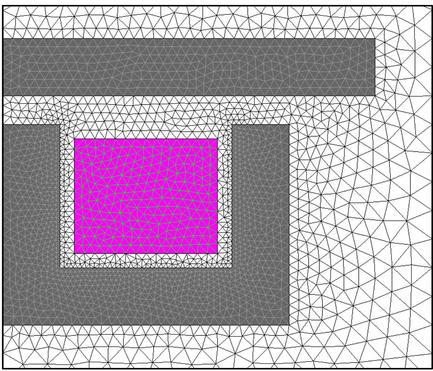
Multi-stranded coil
The simple representation multi-stranded coil allow to simulate multi-stranded wires in a simplified representation: There is no represention of each strand. As it is a simplified representation, some physical phenomena such as skin effect and proximity effects are not taken into account.
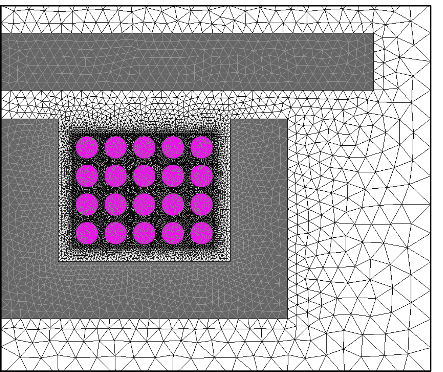
Solid conductor
The solid conductor allow to simulate conducting medium in its real representation. For the winding, each strand must be represented. it takes into account precise local physical phenomena such as skin effect and proximity effects.
Meshed coil
The meshed coils correspond to coils which are meshed bodies and are fully integrated into the finite element domain.
Non-Meshed coil
The non-meshed coil is a 3D coil representation which is not linked to any meshed body (do not belong to the finite element domain). The non-meshed coils should be regarded instead as being superposed to the domain. Analytic Biot-Savart equation is solved to compute the generated magnetic field.
This page explains the main differences between the five possibilities in SimLab to facilitate the choice.
Meshed coils: Coil vs Solid conductor components (Circuit)
- Multi-stranded coils
- Solid conductor
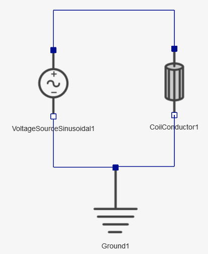
- Coil component in the Circuit
Designer

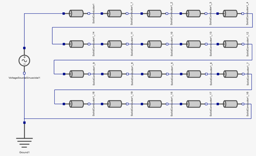
- Solid Conductor component in the Circuit
Designer

The Circuit Designer is available in 2D and 3D Transient Magnetic solutions.
Coil Conductor
Solid Conductor
Comparison
| Meshed Coil region type | Current density | Mesh | Description of the coupled electric circuit | Frequency behavior of Joule losses |
|---|---|---|---|---|
| Solid Conductor |
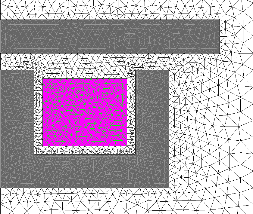
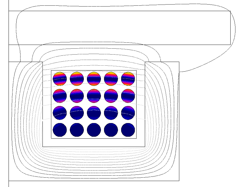 Flux evaluates a non-uniform current density distribution reflecting the skin and proximity effects. |
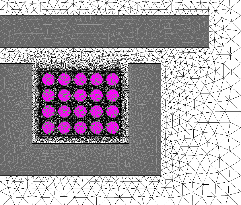 Complex meshes required. |
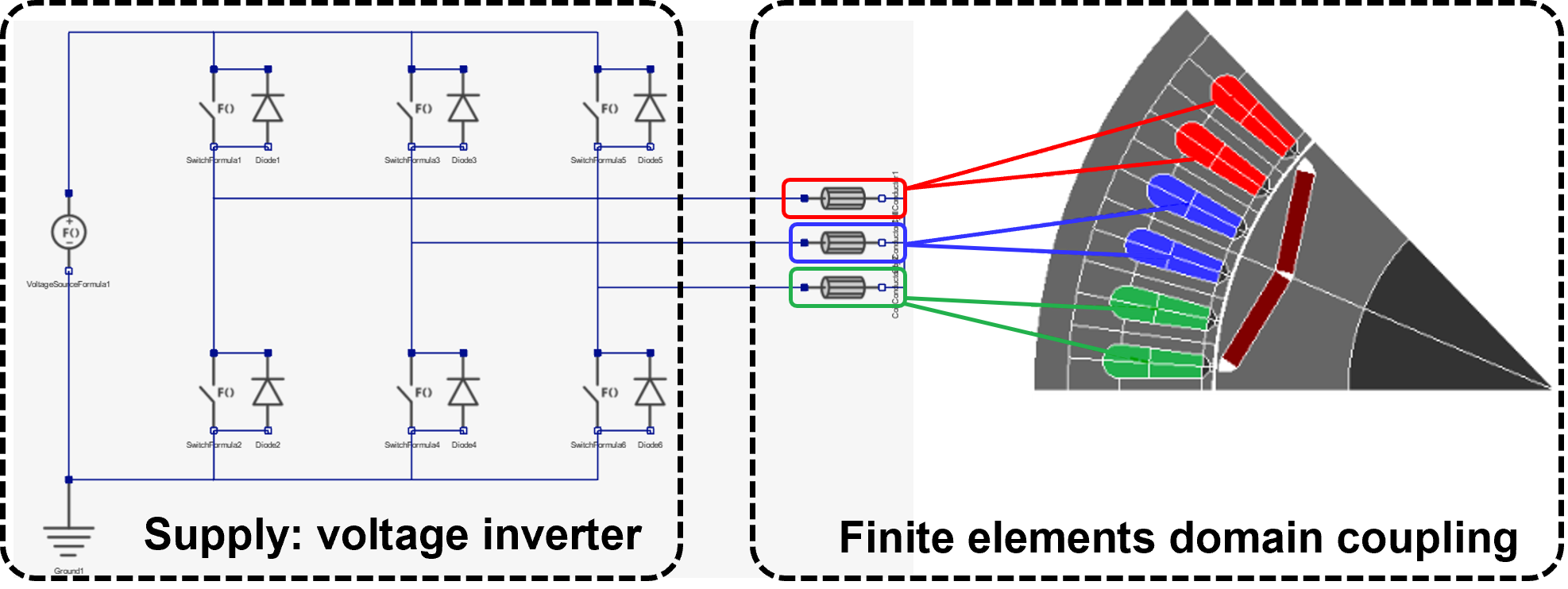
 Potentially elaborate. One FE coupling component required for each Solid Conductor region. |
 Skin and proximity effects fully taken into account, leading to augmented Joule losses at higher frequencies. |
| Coil | 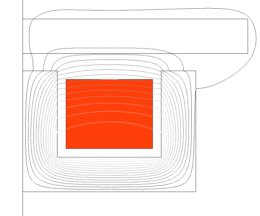 Flux evaluates an equivalent uniform current density distribution. |
 Coarser meshes are possible. |
 Straightforward. Only one FE coupling component required. |
If optional inputs are defined -
Coil fill factor value entered and
Material with Resistivity value
assigned to Coil bodies: Joule losses are non-zero and constant at any frequency. Results are accurate for direct current and low-frequency excitations. |
If optional inputs are not
defined: Joule losses are constant and equal to zero at any frequency. |
Connection
- In 2D: In the Coil and Solid Conductor components dialog boxes, first, surface bodies are assigned. Then, Positive or Negative current orientation is selected. If there are no symmetry and no periodicity, The assignment will be done on two distinct bodies, one with injecting current and another one with leaving current.
- in 3D: In the Coil and Solid
Conductor components dialog boxes, first, volume bodies are
assigned. Then, the terminals assignment is done with one of the two
methods:
- External terminals: It is suitable for opened coil or conductor. Input terminal faces and output terminal faces are selected
- Internal terminals: It is suitable for closed coil or conductor. Input terminal faces are selected. Once the selection done, a default orientation is proposed with an arrow on the graphic. It is possible to reverse it.
Note: For Solid Conductor components, only two terminal solid conductor exist for now. N-terminals solid conductor will be added in the future.
Meshed coil: Imposed Current Coil LBC (No Circuit)

The LBC is available in 2D and 3D Magnetostatic and 2D and 3D Transient Magnetic solutions.
This is a particular case of multi-stranded coil with simplified representation, suitable for simple use cases: The coil bodies are not connected to a circuit. All the physical inputs, including an imposed current value, are entered in the LBC dialog box.
Please refer to the previous paragraph to understand the multi-stranded coil with simplified representation.
In this case, the Joule losses are not computed.
Meshed coil: Passive Solid Conductor LBC (No Circuit)
The Passive Solid Conductor LBC is available in Analysis ribbon:

The LBC is available in 2D and 3D Transient Magnetic solutions.
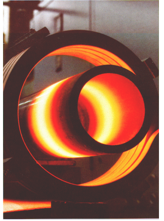
This is a particular case of solid conductor: The solid conductor is not supplied and not connected to a circuit. The solid conductor is "Passive" which means that the only flowing current is an induced current (or eddy current). One typical application is the induction heating, the heated part is modeled as a passive solid conductor.
Meshed coils vs Non-Meshed coils
The meshed coils correspond to coils which are meshed bodies and are fully integrated into the finite element domain.
- Meshed multi-stranded coil, connected to a circuit or supplied by an imposed current
- Solid conductor, connected to a circuit or passive
From a finite element method point of view, the face or volume bodies assigned to a meshed coil belongs to the computational domain and is discretized by finite elements. In consequence, it is possible to evaluate and display local quantities such as the current density, the magnetic induction, and the power loss density inside these bodies.
In 3D applications, however, the description of a coil with an arbitrary shape through a meshed coil may become too complicated, and meshing the associated volume may lead to an excessively large numerical problem. Therefore, 3D Magnetostatic and Transient Magnetic solutions provide the user with an alternate way of specifying a coil in 3D: the non-meshed coil magnetic source LBC.
This variety of magnetic source is an entity superposed to the 3D domain and independent from any meshed surface or volume bodies. In a simulation containing a non-meshed coil, the magnetic induction that it generates analytically with the Biot-Savart law is evaluated. Moreover, the finite element formulation implemented in the software takes this additional field contribution into account in the meshed parts of the domain.
However, and in contrast with the case of meshed coils, post-processing local quantities inside a non-meshed coil is impossible.
Several predefined templates of non-meshed coils are conveniently available for the user, with geometries ranging like Toric coils. A composed coil type exists as well, allowing the user to create a 3D non-meshed coil of arbitrary shape.
The non-meshed coils are current supplied through the circuit Coil component in 3D Transient Magnetic solution and through an imposed current value in the Non-Meshed Coil LBC dialog box in 3D Magnetostatic solution.
For an extended discussion on the use of meshed and non-meshed coils LBC in SimLab, please refer to the Non-Meshed coil page.
Summary comparative table
| SimLab feature | Definition | Mesh and Solving | Post processing | Access |
|---|---|---|---|---|
| Imposed Current Coil LBC |
|
|
Local and global results | All magnetic solutions |
| Coil circuit component |
|
No mesh and good performance in 3D |
|
2D and 3D Transient Magnetic |
| Non-Meshed Coil LBC (3D) |
|
Mesh can be huge and performance bad for 2D and even worse in 3D | Only global results | 3D magnetic solutions |
| Passive Solid Conductor LBC |
|
Mesh can be huge and performance bad for 2D and even worse in 3D | Very fine global and local results | 2D and 3D Transient Magnetic |
| Solid Conductor circuit component |
|
Mesh can be huge and performance bad for 2D and even worse in 3D | Very fine global and local results | 2D and 3D Transient Magnetic |