CAD Based Solutions
Introduction
An EM solution can be defined either with FEM or CAD bodies.
- The FEM based solution requires from the user to manually mesh the bodies. The meshed bodies are then assigned to the solution and it is no longer possible to modify the geometry. Parametric studies with geometrical parameters are then impossible.
- The CAD based solution allows to simplify the model setup and utilize automated meshing capabilities. It is then possible to study, thanks to geometry parameterization, the effect of geometry changes in the model and to carry out DOE studies and optimization.
Note: This page details the CAD based solution. The
other pages in the Electromagnetic part are for now based on the FEM
based solution.
Steps to define a CAD based solution
The steps to define a CAD based solution are:
-
Create the geometry which can be parameterized by using:
- CAD file import
- Sketch
- SimLab geometry operations (primitive objects creation, extrusion, etc.)
Figure 1. Illustration of a 3D parameterized motor model creation in SimLab 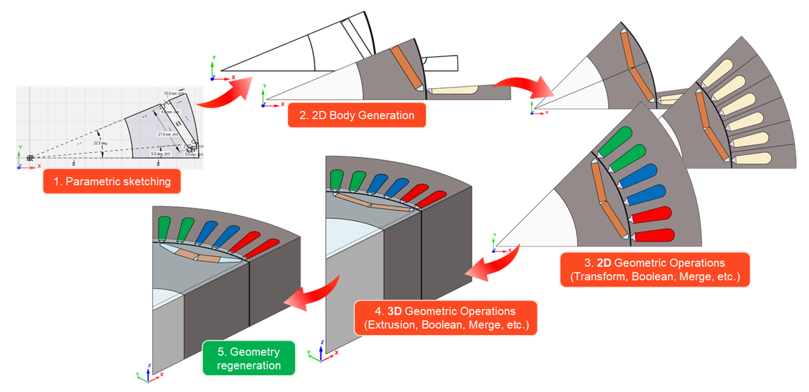
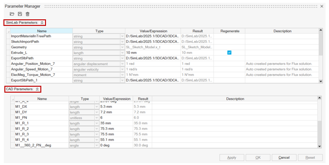
The parameters are listed in the SimLab Parameter Manager:- SimLab Parameters contain the parameters used in SimLab geometry operations and the physical parameters
- CAD Parameters contain the parameters used in the Sketch or the imported CAD file
-
Once the parameterized geometry is created, it is possible to modify the parameters values in the SimLab Parameter Manager to regenerate the geometry. The SimLab Parameters must have the Regenerate check box activated to take into account its modification in the geometry regeneration process.
The geometry modification and regeneration can be done after the mesh and the physics definition.
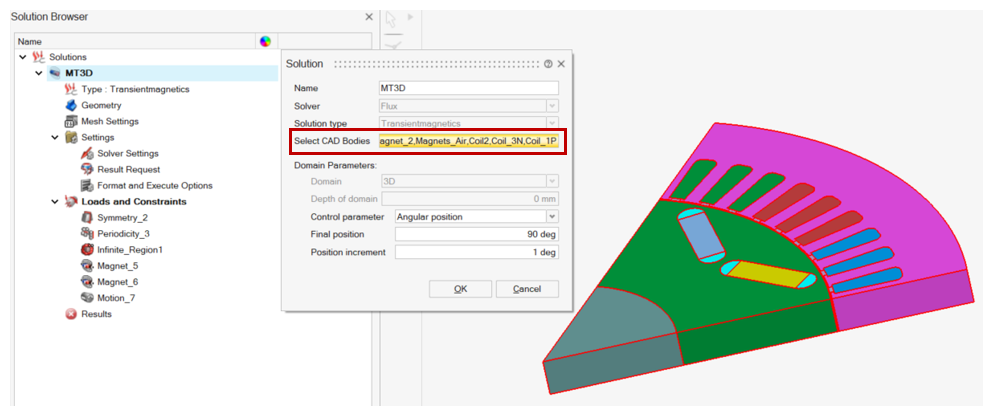
- Create the EM solution and assign the CAD bodies
- Define the physics by assigning the CAD bodies to the materials, Loads and Constraints and the circuit components
- Define the Mesh Settings:
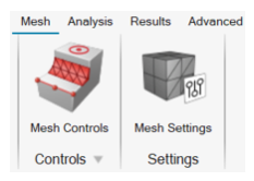
- The Mesh Settings uses:
- In 3D, the EM Mesh tool
- In 2D, either the Motor Mesh tool or the Surface Mesh with a uniform average element size
- It is possible to Create Mesh to check the mesh before solving
Optional: Add Mesh Controls to locally control the mesh.
- The Mesh Settings uses:
- SolveDuring the solving the following processes are executed automatically:
- First, the mesh is created if it does not exist
- Physics will be mapped to respective mesh and exported to the
solver for solvingNote: The physics will be retained on the CAD bodies in SimLab.
- Post ProcessNote: The spatial results (contour, vector etc.) are loaded on the meshed bodies.
- It is possible then to run a DOE to analyze the impact of the parameters value change
Geometrical operations advice
Warnings
- The Regeneration process at parameters modification or at the DOE execution
reproduces all the operations manually done in the model. If the model
setting includes invalid operations, regeneration might fail in some
cases.Note: It is possible to display the operations list (with each operation regeneration status) in the Parameter Browser tab by activating the following option in the Preferences: .
- It is currently not possible to have two CAD based solutions within the same database referring to the same CAD model. The workaround is to have one solution per database.