EM Mesh
![]()
EM Mesh
EM Mesh is a specialized meshing tool designed to mesh 3D electromagnetic models used in Flux solver. It provides options for both Tri/Tet and Extrusive mesh generation, accurately capturing curved features and fine geometric details.
Input
Parasolid CAD bodies.
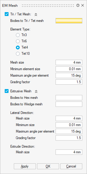
Tri/Tet Mesh
- Bodies to Tri / Tet mesh
Specify the bodies to be meshed using Tri / Tet elements.
- Element Type
The element types supported are:
- TRI3
- TRI6
- TET4
- TET10 (Curved edge)
- Mesh Size
Mesh size refers to the average edge length of the solid and surface mesh elements.
- Minimum element size
Ensures that all surface mesh edges are larger than the specified minimum element size. Topological edges shorter than this value are automatically removed.
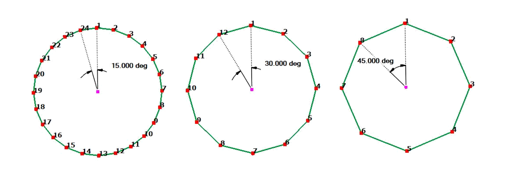
- Maximum angle per element
This Governs the surface mesh density on curved surfaces by controlling curvature approximation.
The default Maximum angle per element is 15 degrees. This will create 24 elements on a circular hole. A better approximation of the surface can be obtained by using a smaller Maximum angle per element. If the Maximum angle per element is increased to 30 degrees, 12 elements will be created on a circular hole.
- Grading factor
The mesh size transition on a surface mesh is controlled by Grading factor. Default Grade Factor value is 1.5. (Between neighbouring elements, element size marches 1.5 times from fine to coarse).
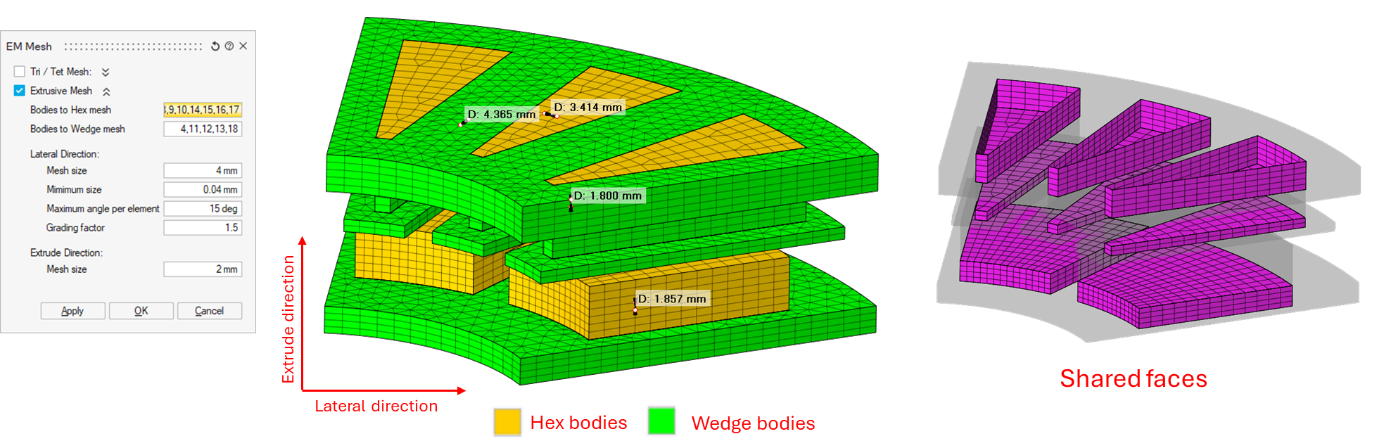
Extrusive Mesh
This option generates structured hexahedral, or wedge meshes for bodies created via extrusion. It ensures shared face connectivity between adjacent volumes and provides automatic pyramid transitions between Hex/Wedge and Tet regions.
If bodies have symmetry mesh control applied, the extrusive mesh will also maintain symmetry across the defined faces.
- Bodies to Hex mesh
Specify bodies to be meshed with hexahedral elements.
- Bodies to Wedge mesh
Specify bodies to be meshed with structured wedge elements.
- Lateral direction
These parameters apply to directions perpendicular to the extrusion direction.
All other parameters are the same as those described under Tri / Tet Mesh, including mesh size, curvature control, and grading.
- Extrude direction mesh size
It is the average mesh size along the extrude direction.
Practical guide
As a first step, it is advised to run the EM Mesh with Tri3/Tri6 element type to generate quickly a surface mesh that can be checked before generating the volume mesh which is much more time consuming.
- For a geometry with planar faces, without or with very few curved faces.
The mesh size has a predominant role to set the average mesh size.
On this linear actuator example, the geometry has no curved surfaces. The mesh size=2mm is set to have a “correct” first mesh.
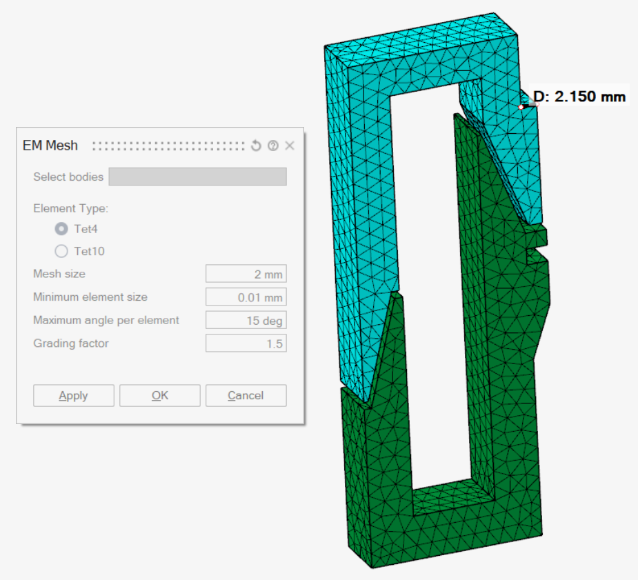
Mesh controls can be created before the EM mesh execution to have a better mesh on the air gap.
- In models with many curved faces like motors, the Maximum angle per element has
a predominant role to set the curved faces mesh.
In such cases, the mesh size should not be too small, otherwise the grading factor will not have any impact on the mesh grading.
An advised mesh size value is the bounding box maximum edge size /10. This value is computed and shown in the Output window when selecting the bodies in the EM mesh tool: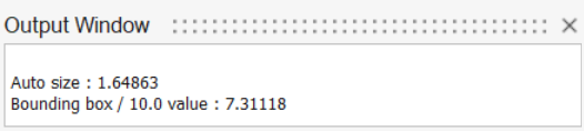
On the motor models, it is necessary to add mesh controls before executing the EM mesh tool. At least, following mesh controls are necessary:
- Use mesh control on the airgap to have a uniform fine mesh.
- If the motor is periodic, use Symmetry Mesh control to have a periodic mesh.
Remark
All the parameters are considered together to set the mesh: the input values must be consistent to each other.
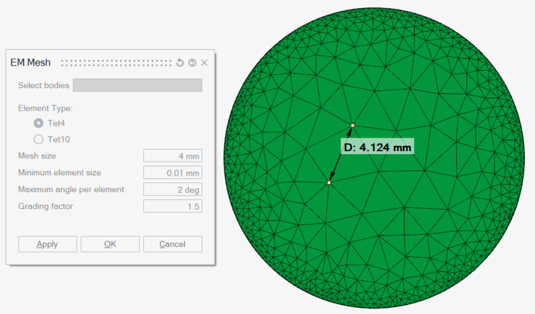
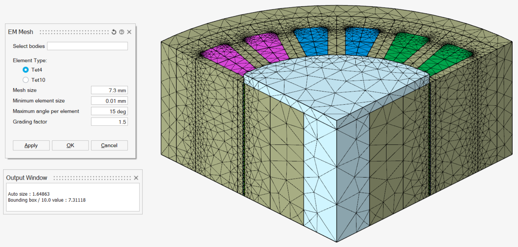
On this cylinder example, with a mesh size=4mm, Maximum angle per element=2deg and a grading factor=1.3, the element size in the middle is 3mm.
In this case, the grading factor must be increased to reach a mesh size=4mm in the middle.