Tet Mesh
![]()
Tet Mesh Parameters
The parameters for Tet4 and Tet10 is shown below.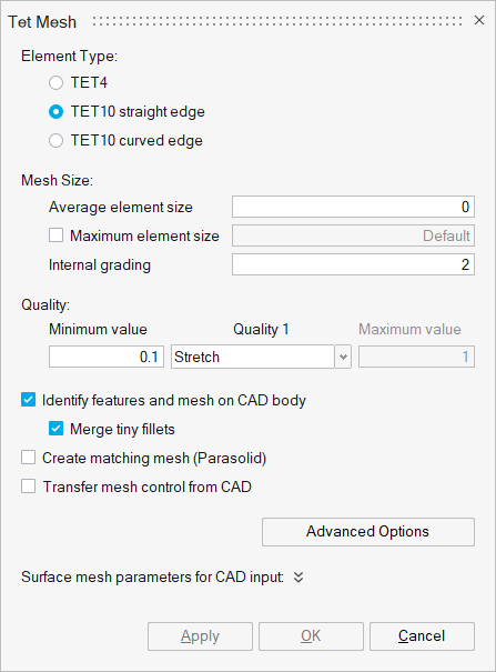
The element types supported are:
- TET4
- TET10 straight edge
This option will result in a Tet-mesh with all element edges being straight (not curved). Also, the mid nodes will be at the middle of the straight edge. This behaviour applies to TET-meshing CAD and FE bodies.
- TET10 curved edge
This option will create a Tet-mesh with the mid nodes on the geometry and therefore the element edges can be curved. This applies to Tet-meshing CAD bodies.
For the FE body, if the input mesh contains mid nodes on the curved surface, then the mid nodes will be maintained as such. For other inputs, mid nodes will be created on the straight edge only.
Mesh Size
- Average element size
The Average element size is the average element edge length of the solid element.
- Maximum element size
When this option is ON, the solid elements generated will have element length less than or equal to the specified Maximum element size. The Maximum element length should not be less than SqRt(2) times the Average element size.
- Internal grading
- The variation of tet mesh inside the body from surface to interior is controlled by the Internal grading. In case of bodies having very fine surface mesh, the grading of tet mesh from fine, at the surface, to coarse as we move in, is obtained based on the grade factor. The default value is 2.0. The first layer of the tet mesh is also graded to reduce the number of elements.
This option is available only for Tet element type.
- Quality 1
The list of Quality 1 type supported are,
- Stretch
- Collapse Ratio
- Tet Collapse
- Fluid Aspect Ratio
- Skew
- Aspect Ratio : Nastran
- Aspect Ratio
Any one of the above quality type can be selected.
The minimum/maximum value of the Quality Type allowed is controlled by the Min/Max value. The default values for each Quality Type is given below,
- Stretch = 0.1
- Collapse Ratio = 0.04
- Tet Collapse = 0.12
- Fluid Aspect Ratio = 5.0
- Skew = 0.02
- Aspect Ratio : Nastran = 20.0
- Aspect Ratio = 5.0
For all the above Quality Types, except Fluid Aspect Ratio, Aspect Ratio : Nastran and Aspect Ratio, the Min value (lower limit) is used (i.e., when Stretch Quality Type with Quality Metric = 0.15 is used, all Tet elements in the output mesh will have Stretch value greater than 0.15.
- Quality 2
This option is supported only for TET10. The list of Quality 2 type supported are,
- Jacobian-Normalized
- Jacobian-Ratio
- Jacobian-Nastran/ABAQUS
- Jacobian-Ansys
Any one of the above quality type can be selected.
The minimum/maximum value of the Quality Type allowed is controlled by Min/Max value. The default values for each Quality Type is given below,
- Jacobian-Normalized = 0.001
- Jacobian-Ratio = 0.1
- Jacobian-Nastran/ABAQUS = 0.001
- Jacobian-Ansys = 0.0333
Identify features and mesh on CAD body will mesh the fillets and cylinders as if the fillet and cylinder mesh controls are applied with the global meshing parameters. For more details, please refer Identify features and mesh.
Merge tiny fillets
It will work with “Identify features and mesh” option and supported only for CAD. For more details, please refer Merge tiny fillets
Create matching mesh (Parasolid)
This option will create matching mesh between Parasolid bodies that are in contact. Matching mesh will be created by connecting Parasolid bodies using Boolean -> Combine operation. For more details, please refer Create matching mesh.
Limitations:
- CAD body – FE body link is not possible.
- Mesh output will always be created in a new model.
Transfer mesh control from CAD
On Tet meshing a FE body, all the body-based mesh controls present on the parent CAD model will be considered. Mapping will be performed based on CAD id.
Limitations:
- This option works if there is only one CAD model in the assembly browser.
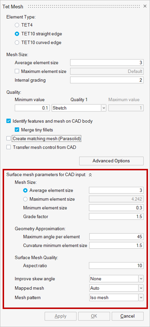
Surface mesh parameters for CAD input is used to control the surface mesh parameters when directly Tet meshing the CAD bodies. For more details about the parameters, please refer Surface mesh parameters
Tet mesh output option for different inputs
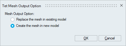
Based on user input Tet mesh output will be created in a new or existing model for CAD / FE body input. Please refer to the surface mesh output option for the detailed explanation.
Limitations
- Replace bodies in the existing model is not supported for bodies assigned with Region mesh control - body break option.
- If input FE assembly has shared faces and output is created in a new model, to maintain the shared faces “Assembly” option must be turned ON. Otherwise, shared faces will not be maintained.
- Whenever the CAD bodies are meshed and the mesh output is replaced in the existing FE bodies which are shared, connectivity will be lost in the output mesh.
- If the input FE body has angular symmetry or edge bias seeding mesh controls, replacing the output in the existing model will delete the above-said mesh controls.
Multi core meshing
Mesher uses single core as default, to perform the meshing. When an assembly has multiple bodies, single core meshing will mesh one body at a time. So the total time taken is the sum of the time to mesh each body. If the hardware supports multiple cores, user can request the mesher to use the multiple cores when meshing. When multiple solids are selected to mesh, the mesher will distribute the bodies between the cores and mesh them simultaneously. This will reduce the meshing time for assemblies with large number of bodies. Note that the amount of physical memory in the machine will also determine the performance of meshing. User can specify the number of cores in File | Preferences | Applications | Options. Currently multi core meshing is supported for Parasolid and Step models.Advanced Options
This option is supported only for the Tet element type and can be viewed and set once the input entities are selected.
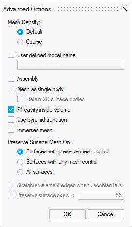
Mesh Density
For regular meshing use Default option. Coarse option is used to reduce the number of solid elements (Tet4 and Tet10) and subsequently the number of nodes. On an average, coarse tet mesh generates ~20% less nodes/elements compared to regular tet mesher.
User defined model name
This option will create the output mesh in a new model or rename the existing model with user given name.
Assembly
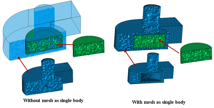
This option is used to tet mesh the assembled FEM bodies. This will maintain the node matching of the shared faces during tet quality clean-up.Mesh as single body
This option is used to tet mesh the selected bodies as a single region. This toggle will be useful for the following cases;
- The individual bodies are not closed, but as an assembly it is closed.
- One body resides inside another body, where we want to include the mesh of the inner surfaces when we generate the tet mesh for the outer body.
- Retain 2D surface bodies: This option is supported along with "Mesh as single body" only. It will retain all the 2D surface bodies that are given as input for tet mesh. Tet mesh will be created in a new body in the same model. The nodes will be shared between the surface and solid bodies. These 2D surface bodies will help to quickly setup the CFD boundary conditions.
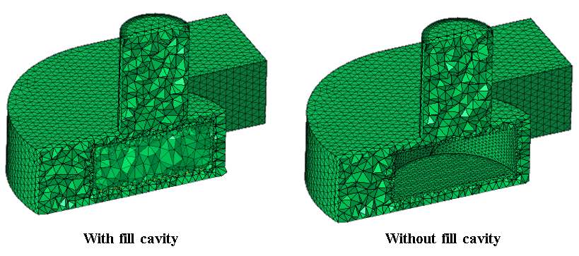
Fill cavity inside volume
By default all the domains in the selected bodies will be tet meshed. If "Fill cavity inside volume" option is turned off, only the outer most volume will be tet meshed.
- Case 1: All domains in a single body
- Input
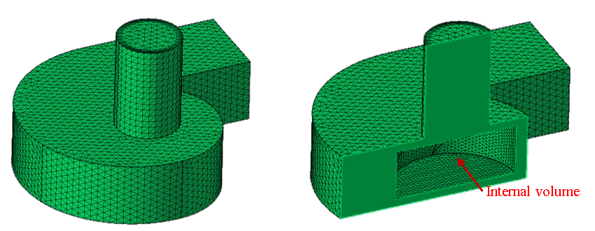
- Output
If outer and inner domains are two separate bodies, "Mesh as single body" option must be used with "Fill cavity inside volume" to get both the domains filled without overlap.
- Input
- Case2: Each domain as separate body
- Input
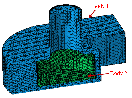
- Output
- Input
Use pyramid transition
During tetrahedral meshing of finite element (FE) bodies containing quadrilateral (Quad) surface elements, the default behaviour is to convert Quad elements to triangular (Tri) elements prior to generating the tetrahedral (Tet) volume mesh. Enable the Pyramid Transition option to retain the Quad elements on the surface and ensure a smoother transition to the Tet mesh. This option inserts a single layer of pyramid elements between the Quad surface mesh and the Tet volume mesh, facilitating a more accurate representation of the geometry.
![]()
Limitations:
- By default, the resulting mesh is generated within the original body.
- The feature is not supported for bodies composed exclusively of quadrilateral surface elements.
- Quadrilateral faces must not be shared with adjacent shell bodies.
Immersed mesh
This option must be used along with Immersed Refinement Mesh Control.
Preserve Surface Mesh On
- Surfaces with preserve mesh control
Faces with Preserve Mesh Control will be preserved.
- Surfaces with any mesh control
Faces with the any Mesh Control will be preserved. For example, if fillet mesh control is applied to the fillets, even those faces will be preserved during tet meshing.
- All surfaces
All the faces will be preserved. It means the entire surface mesh will be preserved.
>Straighten element edges when Jacobian fails
This option is supported only for TET10 curved edge element type. Enabling this option will give priority to Jacobian quality over preserving mesh on the geometry when Tet-meshing. Therefore, elements failing in Jacobian quality will be corrected by straightening element edges, by ignoring the options to preserve mesh on the faces.
Preserve surface skew
Preserve surface skew value can be set, so as to not degrade the surface skew quality during TET skew cleanup.
Layer Meshing
Layer Meshing is used to generate layers of Tet elements along thin regions.
Layer meshing will be done for bodies which contains Volume Layer Mesh Control.