CFD Mesh
![]()
Description
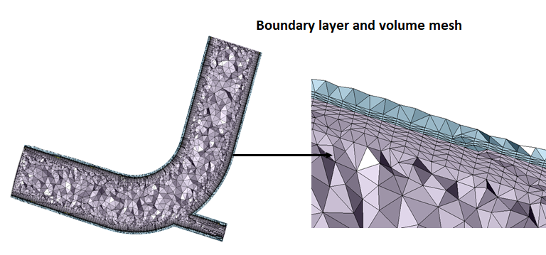
CFD Mesh option is used to generate the boundary layers from the fluid wall faces and Tetrahedral elements for the interior of the bodies. CFD Mesh can be generated using two different options namely the Body and Face. Input to CFD mesh is both CAD and FEM with lower order mesh (TRI3).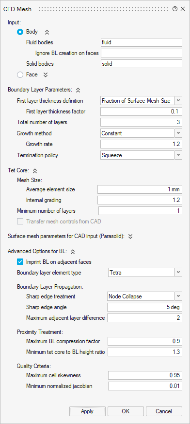
Input Body
The requirement for Body is that all the surface mesh bodies must not have any free edges, i.e., they are closed bodies and could have shared with other bodies. When a body encloses another body either partially or fully, there should be clearly demarcated boundary in between them, i.e., shared faces should exist in between them.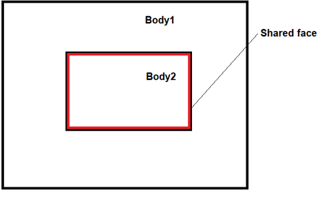
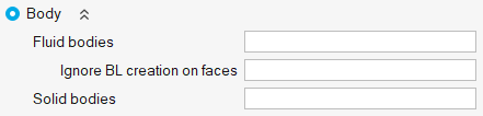
Ignore BL creation on faces: Select faces of fluid bodies on which boundary layer generation needs to be ignored. For example, Inlets, Outlets and shared faces between fluid bodies may not require a boundary layer.
Solid bodies: Select bodies to generate Tet mesh. The bodies modelled as solids in the simulation does not require the boundary layer.Input Face
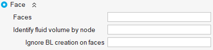
Unlike the body-based option, the face-based option is more versatile. It can handle faces from bodies that may or may not be completely watertight. The selected faces might fall into one or both of the following categories:
- Watertight Bodies: The bodies are watertight and contain one or more fluid
volumes. In below image, F1 and F2 are fluid volumes.
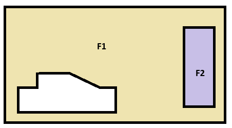
- Non-Watertight Bodies: The bodies are not watertight, but selecting all the faces can form watertight volumes.
Faces: Select all the faces of the bodies to generate a CFD Mesh.
Identify fluid volume by node: Define a node inside a closed volume. The closed volume will be considered as a Fluid body and boundary layers will be generated on the faces of that volume. When there are more than one fluid volumes, define node inside each volume.
Ignore BL creation on faces: Select faces of fluid bodies on which boundary layer generation needs to be ignored.
Selected BL and No BL faces should form a closed volume.Boundary layer parameters
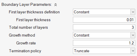
First layer thickness definition: First layer thickness can be controlled by using any one of the following two methods,
- Constant: Constant thickness will be maintained on the entire first layer.
- Fraction of Surface Mesh Size: The first layer height for each element equals the average element size multiplied by the given factor. This option is useful when the mesh size of 2D elements varies significantly and a constant first layer height is not needed. A smooth BL to tetra mesh transition for all elements can be achieved by using this option.
Total number of layers: Determines the total number of layers to be created.
Growth Method:
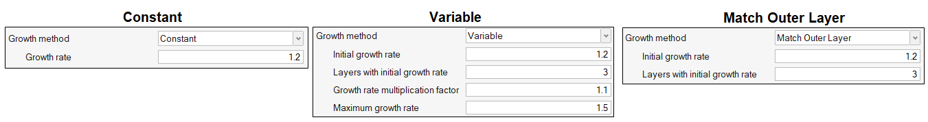
- Constant: This will determine boundary layer growth based on a constant ratio such as growth rate.
- Variable: This will be used to define the growth of BL beyond certain number of layers. An initial growth rate and number of layers with initial growth rate must be defined. In above settings, by default, the first three boundary layers grow based on initial growth rate described above. However, subsequent layers grow by the growth rate multiplied by the Growth rate multiplication factor. Thus, if t is the initial thickness, r is the initial growth rate, and a is the growth rate multiplication factor, then the thicknesses of the successive layers are t, t*r, t*r*(r*a), t*r*(r*a)^2, and so on. This option acts as a growth rate on the growth rate, but only after the first few initial boundary layers.
- Match Outer Layer: First few layers from the wall grow based on growth rate and remaining layers will be adjusted such that the final BL size matches with the core volume mesh size. This method helps to obtain a smoother transition from boundary layer mesh to volume mesh.
Growth Rate: Layer height transition between each layer will be controlled by Growth Rate.
Termination policy: Determines what to do when BL has reached the defined criteria such as layer thickness and growth rate.
- Truncate: This helps to chop off the BL if elements reach the aspect ratio criteria.
- Squeeze: It allows the BL to grow until the neighbouring elements begin to grow, even if elements reach the aspect ratio criteria with GR =1.
Tet Core
One can use this option to Tet mesh the inner domain along with the boundary layer. Region mesh control is supported for TET core mesh.
Minimum number of layers
This option allows to specify the minimum number of layers that must be present within the tet core. This option is only available for ASML boundary layer mesh option.
Transfer mesh control from CAD
On Tet meshing a FE body, the following mesh controls, if present on the parent (CAD) model, will be considered.
- Body Mesh Control
- Volume Layer Mesh Control
- Region Mesh Control
- Symmetry Mesh Control
- Boundary Layer Mesh Control
Mapping will be performed based on the CAD ID.
Limitation:
- This option works if there is only one CAD model in the assembly browser.
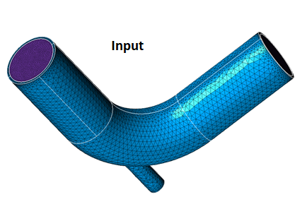
Example
Advanced Options
The options available under Advanced will be used to control the quality and growth of BL under certain circumstances like when BL meets with cracks and thin sections.
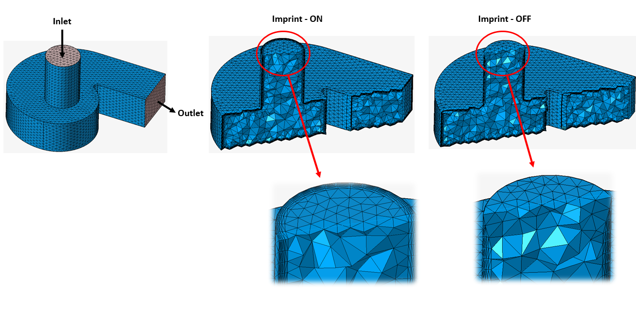
Imprint BL on adjacent faces
- ON: It allows mesh modification in No BL surfaces. Boundary layers will be imprinted on these adjacent No BL surfaces.
- OFF: Prevents the modification of boundary elements in No BL surfaces.
In below example, inlet and outlet are No BL faces.
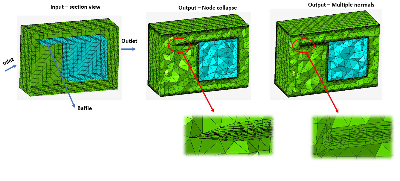
Boundary Layer Propagation
- Sharp edge treatment: Controls the BL at sharp corners which falls under the
specified sharp edge angle.
- Node collapse: Collapses the BL at sharp corners.
- Multiple Normal: Grows multiple normal around sharp corners which are
below the defined angle. If two adjacent elements enclose an angle smaller than
the threshold (sharp edge pointing inside the volume), normal will be computed
on that edge and the boundary layer will consider those normal.
- Sharp edge angle: This defines the limit of sharp edge angles below which the BL will be collapsed.
- Max adjacent layer difference: Controls the maximum layer difference between adjacent elements. This parameter helps avoid situations where all BLs collapse at once, and also provides smooth BL transitions in cases of BL truncation. A good value for this parameter is 1/4 of the total BL layers. The value specified also depends on layer height.
Proximity Treatment
- Maximum BL Compression: This helps in BL compression or squeezing, when there is no enough space available to grow BL. The BL will try to compress by the max BL compression factor first. For example, if the original total BL height is defined as 1, with a 0.4 max BL compression, the BL layers will try to be compressed until 0.6 of the total height is reached. Once the BL is compressed to this value, the mesher will start chopping off layers if there is not enough space. A value of zero enforces no BL compression, which is useful when you want to maintain the BL height; a value of one enables the maximum possible compression. Recommended range: 0-0.6
- Minimum Tet core to BL height ratio: This Controls the minimum height of the tet core as a factor of the final layer height. After creating the BL in close proximity, there will be a small space available for tetra mesh. This results in high aspect ratio tetra elements. Recommend value: 1.3 (default).
Quality Criteria
- Maximum cell skewness: Chops off BL cells exceeding the defined maximum cell skewness. This parameter prevents the generation of highly skewed elements. The tetra mesher sometimes creates better quality elements compared to the BL mesher. If your input 2D mesh has bad element quality and topology, it is recommended that you define a higher value. Recommended range: 0.8 - 0.95
-
Minimum normalized Jacobian: Chops off BL cells exceeding the defined minimum normalized Jacobian. This parameter prevents the generation of negative elements. Recommended range: 0.05 - 0.2
Generate BL only
Turn ON this toggle to generate BL only. Inner shell will not be TET meshed.
- The following mesh controls are supported for both FE and CAD input.
- Boundary layer mesh control
- Region mesh control
- Symmetry mesh control