Switch components
The following are the circuit components supported as of SimLab:
| Component | Icon | Description |
|---|---|---|
| Switch square/formula | Control components, orientation affects the computation. |
Introduction
The switch component is a semiconductor component available for transient solutions. It deals with turning the component states (on or off) depending on a specific set of commands.
In the switch square user defines the pulse characteristics according to which the switch is controlled. While in case of the switch formula user can define a formula and if this formula is greater than zero the on state will be activated.
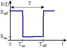
Square switch
Below is the definition of the square switch:
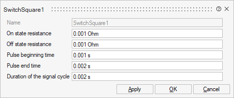
On state resistance: resistance when pulse it at maximum
Off state resistance: resistance when pulse it at minimum
Pulse beginning time: beginning of pulse signal
Pulse end time: The total time of the pulse signal
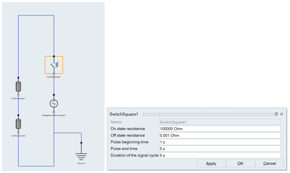
Square switch Example
For the following circuit with a sinusoidal voltage source connected to a simple coil conductor components, a square switch is defined with the following pulse characteristics.
Then the voltage of the source and the coil conductors is shown in the below image.
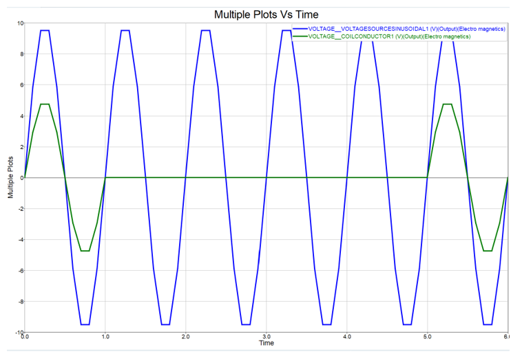
As it can be seen the voltage at the coils for the time between t = 1s and t = 5s is negligible because the switch is turned ON during this time.
Formula switch
The dialog box of switch formula is as below:
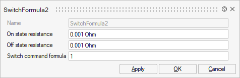
On state resistance: resistance when pulse it at maximum
Off state resistance: resistance when pulse it at minimum
Switch command formula: here user can specify a formula for control of the on and off state. If the given formula evaluates to greater than zero then switch is turned on.
The Valid(x,x1,x2) function returns:
- 1 if x is in [X1 , X2[
- 0, otherwise
Formula switch Example
In case of transient application it is also possible to define a rectangular pulse function described in the figure like:
Valid(TIME, T1 , T2 )

where:
- TIME is the parameter time
- T1 is the instant of the pulse start = [0, T1] the switch is OFF
- T2 is the instant of the pulse end = [T1, T2] the switch is ON