Conductor component
The following are the circuit components supported as of SimLab:
| Component | Icon | Description |
|---|---|---|
| Conductor | FEM coupling components, orientation affects the computation. |
Introduction
The conductor components are used to define the coupling between the circuit and FE domain. Apart from the usual line edit inputs, users need to select bodies from the FE domain to establish the coupling with the finite element analysis.
![]()
From the physical point of view, a conductor is a thick conductor, where the effect of the eddy currents must be considered. The skin depth has a value comparable to or smaller than the conductor cross-section, and the current density is non-uniform on the conductor cross-section.
The basic relation linking the current I, the voltage U and the flux Φ is given below.
The current flowing through a conductor component is the total current I flowing through the correspondent conductor region of the finite element domain.
The voltage at the terminals of a conductor component is the voltage U between the front and the back faces of the modeled solid conductor region.

Where R is the resistance of the conductor and phi is the flux embraced by the conductor.

Dialog box in MT2D
The dialog definition of the conductor component in MT2D looks as follows:
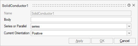
- Body: selection of body/bodies that represent the conductor in the FE domain
- Series/Parallel: defines if the connection is series or parallel or number of conductors in parallel
- Current Orientation: Positive or negative. For 2D this is inside the plane or out of the plane.
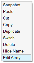
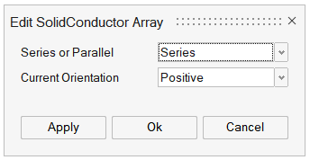
Edit Array
 |
 |
| Right Click | Edit SolidConductor Array |
Added an Edit Array option in MT2D right-click that allows users to edit multiple Conductor components input more efficiently. When users select multiple conductor components and right-click, they can access the Edit Array option. This option opens a dialog that enables them to assign values to the respective dialogs of the selected components without the need to open each dialog individually.
Dialog box in MT3D and MAC3D
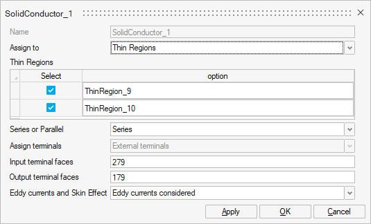
The dialog definition of the conductor component in MT3D and MAC3D looks as follows:
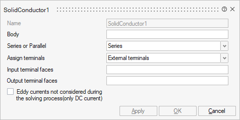
- Body: selection of body/bodies that represent the
conductor in the FE domainNote: It's possible also to select a group of faces previously created (Create Group).
- Connection type: defines if the connection is series or parallel or number of conductors in parallel
- Assign terminals: User have the choice between
External terminals or Internal
terminals to define the connection between the conductor
component circuit terminals and the FE domain.
- External terminals, the user should select
:
- the Input terminal faces
- the Output terminal faces
Once the faces selected, an arrow on each terminal shows the terminals orientation.
- Internal terminals, the user should select
only the Input terminal faces.
Once the faces selected, an arrow on the terminal shows the terminals orientation. It is possible then to reverse the orientation with Reverse Orientation.
- External terminals, the user should select
:
-
Eddy current not considered during the solving process (only DC current): it is possible to not consider the eddy currents (if not needed) to reduce the solving time.
Note: In a 3D AC Magnetic solution, there are 3 choices about the Eddy current and skin effect: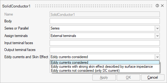
- Eddy currents considered
- Eddy currents with strong skin effect described by surface impedance: see the dedicated page Conductor described by Surface Impedance
- Eddy currents not considered (only for DC current): it is possible to not consider the eddy currents (if not needed) to reduce the solving time
Possible configurations
The conductor component in the circuit designer allows to define all configurations:- active conductor which is supplied by current or voltage source
- and also passive conductor which is not supplied by any source but have only eddy currents generated by the magnetic field.
If user wants to use a passive conductor, a load and constraint named Passive Conductor exists and allows to define very easily a passive conductor without circuit creation.
Conductor defined by conducting Thin Regions in MAC3D
In MAC3D solution, Thin Region load and constraint of Hyperbolic current conductor type is available.
Once the Thin Region(s) created, it is possible to connect it to the circuit through the Conductor component: