Auto Circuit Creation
![]()
Introduction
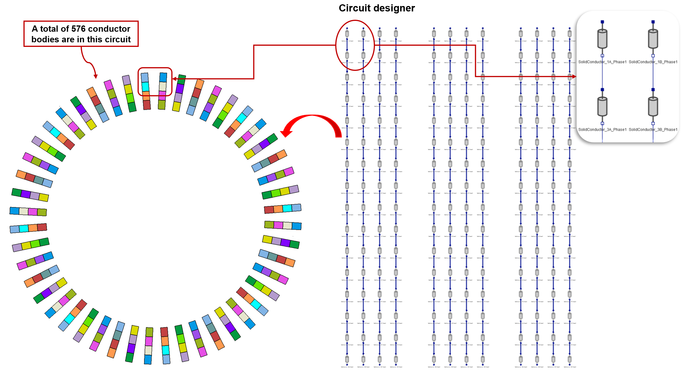
This tool facilitates the generation of the circuit for the given hairpin windings automatically. It supports both CAD and mesh bodies.
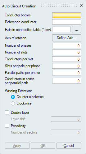
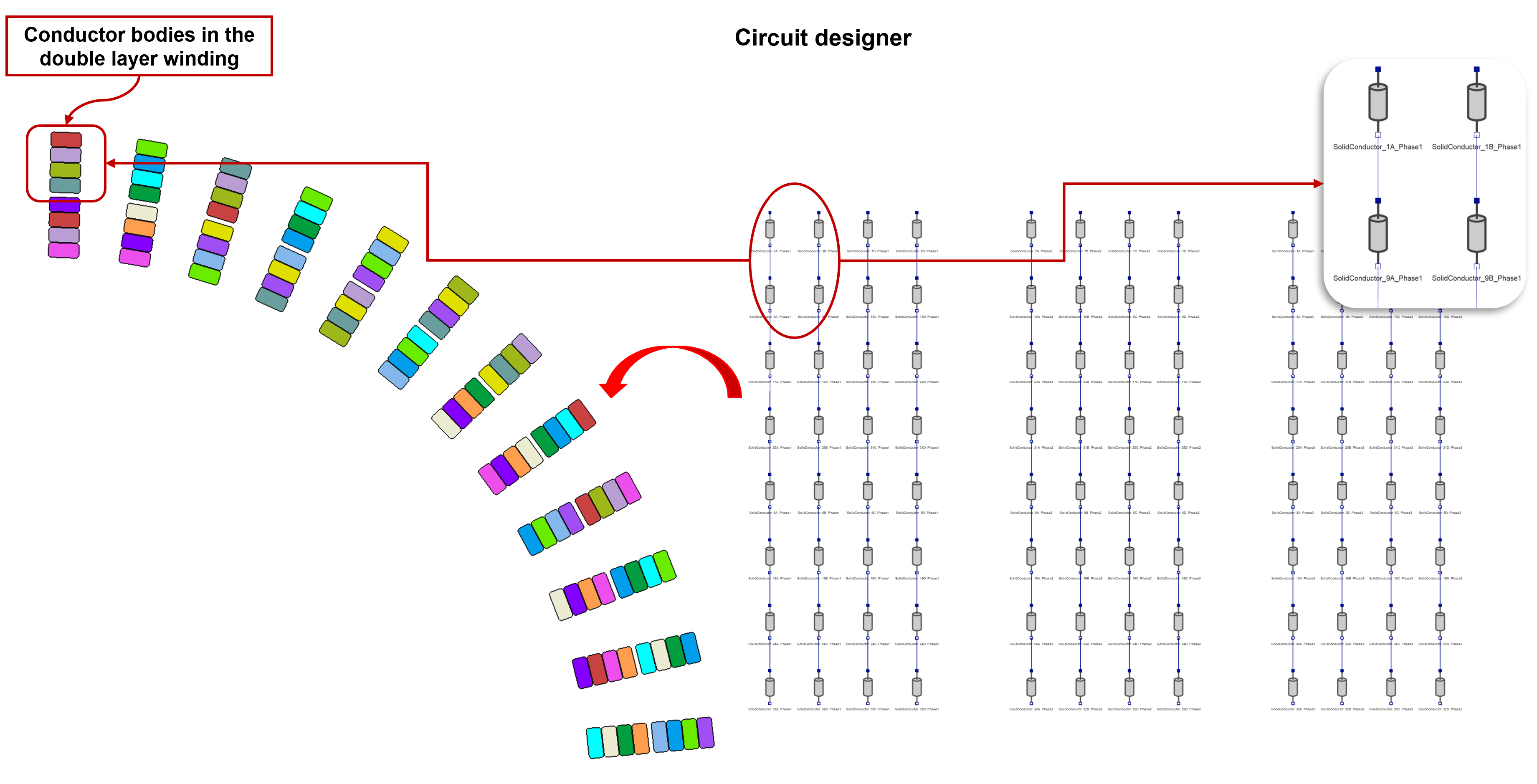
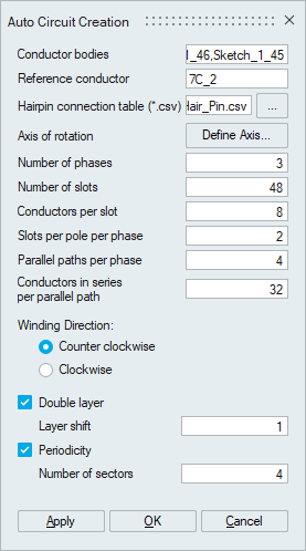
- Conductor bodies
Select all the sheet bodies associated with the solid conductor as the input. For each conductor, the corresponding circuit element is created based on the hairpin connection table.
- Reference conductor
Select the outermost conductor in the first slot of the reference phase.
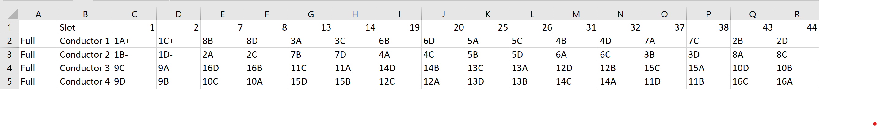
- Hairpin connection table
Input a CSV file defining the hairpin connection table.
- Axis of rotation
Define the rotation axis of the conductor bodies.
- Number of phases
It defines the number of phases of the electrical circuit. This tool is supported only for 3-phase and 5-phase motors.
- Number of slots
It defines the number of stator slots.
- Conductors per slot
It defines the number of conductors through a slot.
- Slots per pole per phase
It defines the number of slots per pole per phase.
- Parallel paths per phase
It defines the number of parallel paths per phase.
- Conductors in series per parallel path
It defines the number of conductors in series per parallel path.
- Winding Direction
It defines the phase sequence assigned to the windings. The phase sequence would be either counterclockwise or clockwise direction.
- Double layer
Turn on this toggle to consider the given inputs as a double-layer winding.
- Periodicity
Turn on this toggle to consider the given inputs as a periodic winding. For this, the user specifies the number of sectors value that describes the number of parts required to assemble the entire motor. It must be consistent with the input conductor bodies.
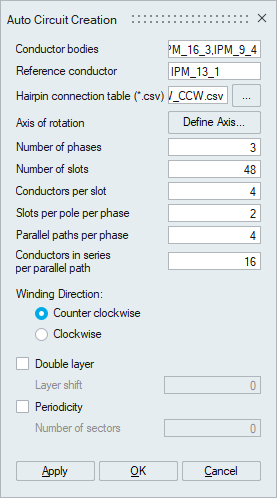
Example 1:
Input CSV file:
Output:
Example 2: Double layer and Periodicity
Input CSV file:
Output: