Non-Meshed Coil
What is a Non-Meshed Coil
A Non-Meshed Coil is a 3D graphical entity of circular, rectangular or more complex shape, which superposes to the mesh and is independent from it.
The computation of the magnetic field created by the distribution of current is then carried out using the Biot and Savart formula in an analytic or semi-analytic way.
A Non-Meshed Coil is not a part of the geometry, i.e. it is not formed of points, lines, faces and volumes. Therefore, it will not be taken into account by the geometric construction and the mesh generator. You can describe it before or after generating the mesh.
The Non-Meshed Coil is a load and constraint available on all 3D magnetic solutions.
Interest and limitation of Non-Meshed Coils
The main interest of using Non-Meshed Coils is to improve the performance of meshing and solving processes.
The main limitation of using Non-Meshed Coils is that the simulation is less precise than using meshed coil (no proximity effect, no skin effect). Also, it is not possible to post process local quantities on the Non-Meshed Coils.
Types of Non-Meshed Coils
The different types of Non-Meshed Coils available through the submenu of the Non-Meshed Coil... button are:
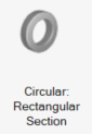
- Four predefined shape coils with circular or rectangular
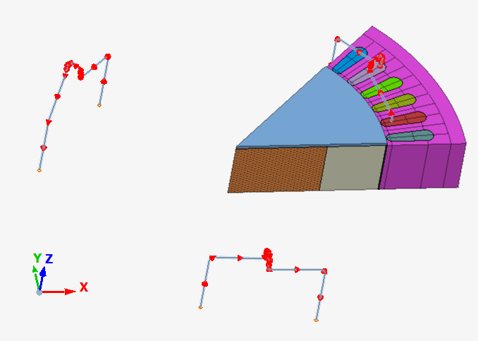
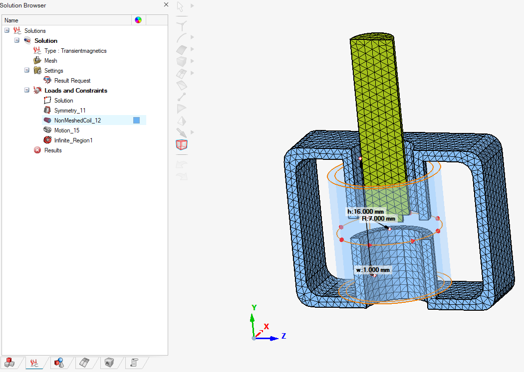
shape and with disc or rectangular section:Here is an example of Circular Non-Meshed Coil with rectangular section on a linear actuator:
Circular coil with disc section Circular coil with rectangular section Rectangular coil with disc section Rectangular coil with rectangular section 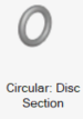
- Composed coils: Composed coils are ones which complex shape is defined by
the user. The section is circular or rectangular.The shape of the coil is the path (open or closed) composed by a set of points. The connecting elements between the points are built on the basis of straight segments with taking into account of the curves if they exist.
Composed coil with circular section Composed coil with rectangular section 
 Here is an example of composed Non-Meshed Coil with circular section:
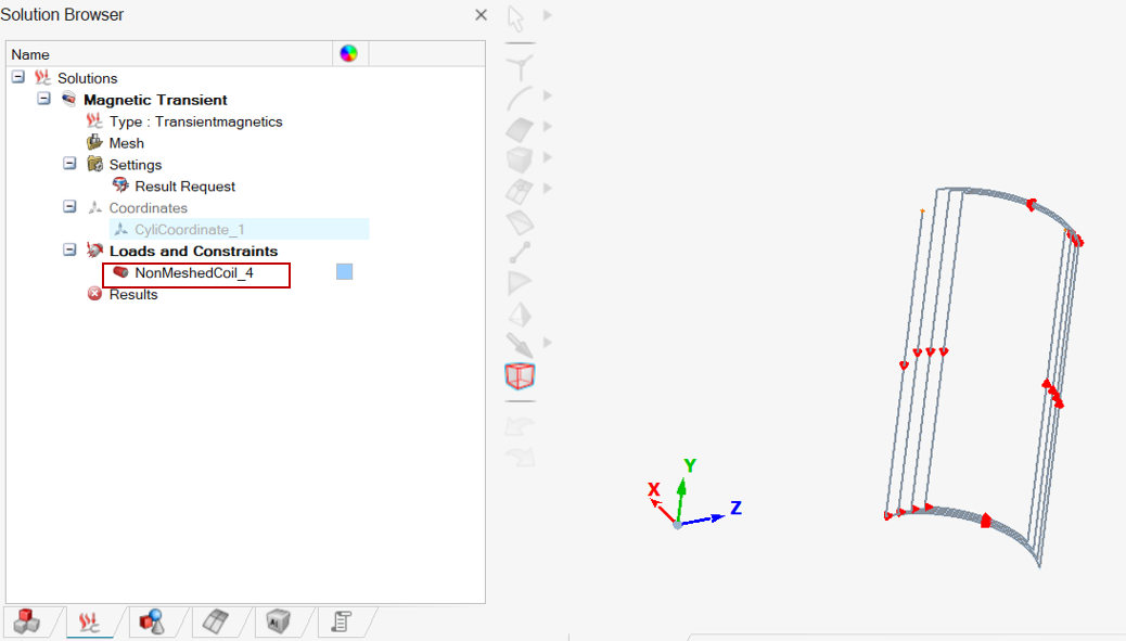
Non-Meshed Coil geometrical definition

The coil path line is the line that defines the shape of the coil. It is also called the neutral axis.
- For the circular shape, through a radius value between the center and the coil path line
- For the rectangular shape, through a height and a width values taken between
two outermost points on the coil path line, on the two directionsNote: Images are available in next section.
For composed coil, the coil path line is defined by a list of points coordinates values, with a possible curvature radius value on each point.
The section is the surface of the coil perpendicular to the coil path line.
The coil path line passes by the center of gravity of the section.
How to create and modify a coordinate system
The coordinate system creation is needed to define the direction and the position of some types of Non-Meshed Coils: Composed and Rectangular.
To create rectangular or composed Non-Meshed Coils, a coordinate system is required.
By default, Global coordinate system is taken.
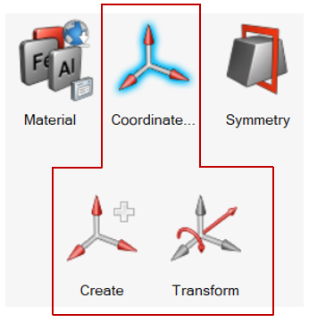
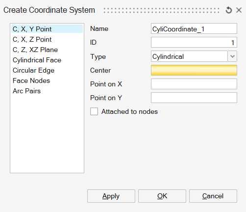
If the Global coordinate system is not suitable, a new local coordinate system must be created by using first Create command.
This command allows to create a rectangular or cylindrical coordinate system (spherical is not managed yet for Non-Meshed Coils) by picking meshed geometrical entities (nodes, meshed edge, meshed face,…).
For more details, please refer to the documentation on coordinate systems Create
Once the coordinate system creation done, it is possible to Transform the created coordinate system either by translation or rotation.
The Transform command allows either to modify a coordinate system or to duplicate it by translation or rotation.
For more details, please refer to the documentation on coordinate systems Transform.
Predefined shape Non-Meshed Coils dialog box for MT3D and MAC3D solutions
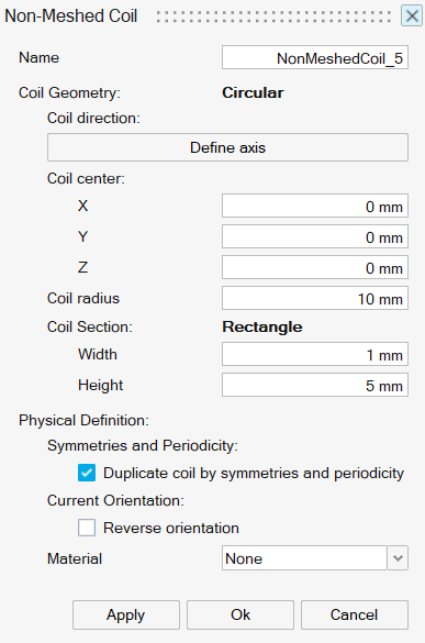
Predefined shape Non-Meshed Coils are defined by two coil path shapes: circular or rectangular and two section shapes: disc or rectangular.
Here are two dialog boxes to get an overview of all the possible inputs:
| Circular coil with rectangular section | Rectangular coil with disc section |
|---|---|
 |
 |
Each Non-Meshed Coil is defined by geometrical and physical inputs.
In MT3D and MAC3D, the physical inputs are mainly defined in the circuit designer coil component. The Non-Meshed Coil dialog box contains mainly geometrical inputs.
- For circular shape coil:
- Define axis: definition of the coil axis direction. The axis is picked graphically.
- Coil center: definition of the coil center by entering its coordinates values in the global coordinate system.
- For rectangular shape coil:
- Coordinate system: Selection of the
coordinate system. The Z axis of the coordinate system defines the
coil axis. The coil is centered on the coordinate system center.
By default, Global coordinate system is taken.
Note: If the Global coordinate system is not suitable, a new local coordinate system must be created. For more details on coordinate system creation and modification, please refer to the section How to create and modify a coordinate system above.
- Coordinate system: Selection of the
coordinate system. The Z axis of the coordinate system defines the
coil axis. The coil is centered on the coordinate system center.
- For circular shape coil: Enter the Coil radius value defined by the distance between the coil center point and the coil path line.
- For rectangular shape coil:
- Enter the coil Height and Width values defined by the distance between two outermost points of the coil path line, on both directions. The height corresponds to coordinate system Y axis direction, the width to X axis direction.
- Enter the Coil fillet radius value to create a fillet on each coil corner.
| Circular coil (rectangular section) | Rectangular coil (disc section) |
|---|---|
 |
 |
- Disk section is defined by Coil section radius value
- Rectangular section is defined by Coil section height and Coil section width . The height corresponds to coil axis direction and the width to the other direction.
| Circular section | Rectangular section |
|---|---|
 |
 |
Once the geometrical definition done, the physical inputs are entered:
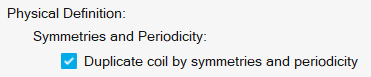
- Symmetries and periodicity / Duplicate
coil by symmetries and periodicity:
Choice to duplicate or not the coils with respects to the symmetries and / or periodicity.
Please refer to the section Symmetry and periodicity with Non-Meshed Coil below.
By default, the duplication is enabled which is the most common configuration.
- Coil current orientation / Reverse
orientation:
By default a current orientation is proposed (please see the preview). It is possible to reverse it.
- Material is an optional field to select a material with a resistivity value in order to compute the Joule losses. If a material with resistivity value is selected, Coil fill factor value in ]0,1] must be entered in the associated circuit coil component.
When clicking on Ok, the Non-Meshed Coil load and constraint entity is created in the solution Loads and Constraints data tree.
Composed Non-Meshed Coil dialog box for MT3D and MAC3D solutions
The composed Non-Meshed Coil is a free shape Non-Meshed Coil defined with points coordinates. The section is defined in the same way of the predefined shape Non-Meshed Coils.
Here is the dialog box of the composed coil with disc section:
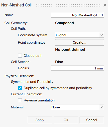
Each Non-Meshed Coil is defined by geometrical and physical inputs.
In MT3D and MAC3D, the physical inputs are mainly defined in the circuit designer coil component. The Non-Meshed Coil dialog box contains mainly geometrical inputs.
- Coordinate system: Selection of the coordinate system
where the points coordinates are defined. By default, Global coordinate
system is taken.Note: If the Global coordinate system is not suitable, a new local coordinate system must be created. For more details on coordinate system creation and modification, please refer to the section How to create and modify a coordinate system above.
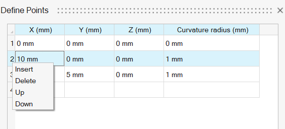
- opens a second box called Define
Points to enter the points coordinates defining the coil
path line. The curvature radius (fillet radius) is also entered for each
point (0 if no curvature). Here are some images to explain the curvature
radius:
Composed coil with closed path, described by 3 points Composed coil with open path, described by 3 points 

a curvature radius R = 0 a curvature radius R <> 0*
is associated to the point P 2
Note: * The value of a curvature radius R in a specified point must be between 0 and the minimum of the distances (the distance between this point and the point which precedes it and the distance between this point and the point which follows it).It is possible to enter manually the values or import a .csv or .txt or .dat file containing all the data through Import... button. The file should contain the data in the following format: 4 columns (for the coordinates values in X, Y and Z directions of the selected coordinate system and the curvature radius value). The columns can be separated by one of the following separators: semicolon ';', comma ',', space ' ' and tabulation '\t'.
In the Define Points dialog box, it is possible to manage each line of the data. The tools are available in a contextual menu, when right-clicking on the line number. User can:- Insert a new empty line before the selected line
- Delete the selected line
- Up the selected line above the previous line
- Down the selected line below the following line
 While entering the points coordinates and curvature radius values, several checks are done instantaneously to verify that the Non-Meshed Coil geometry is correctly defined. The error messages appear as soon as an error is detected on the Point status part.Note: Some errors are not catched on the Point status (not detectable or not implemented yet). User has to pay attention by checking visually the coil preview.
 - Closed path checkbox: Choice of closing or opening the coil between the first and last points, depending on its representation with respect to symmetries and/or periodicity: The coil must be opened if the two points are on a symmetry or periodicity plane. Otherwise the coil must be closed.
- Coil section:
- For disk section, Coil section radius is entered
- For rectangular section, Coil section height, Coil section width are entered. The rectangular section orientation in the section plane is defined automatically from the coil path points. More precisely, the direction change from a segment to another must be done around one of the two directions of the coil section. The first axis of direction change is taken for Height or Width. Please check the preview to identify them.
Circular section Rectangular section
Once the geometrical definition done, the physical inputs are entered:
- Symmetries and periodicity / Duplicate
coil by symmetries and periodicity:
Choice to duplicate or not the coils with respects to the symmetries and / or periodicity.
Please refer to the section Symmetry and periodicity with Non-Meshed Coil below.
By default, the duplication is enabled which is the most common configuration.
- Coil current orientation / Reverse
orientation:
By default a current orientation is proposed (please see the preview). It is possible to reverse it.
- Material is an optional field to select a material with a resistivity value in order to compute the Joule losses. If a material with resistivity value is selected, Coil fill factor value in ]0,1] must be entered in the associated circuit coil component.
When clicking on Ok, the Non-Meshed Coil load and constraint entity is created in the solution Loads and Constraints data tree.
Coil physics in the circuit designer (MT3D and MAC3D)
In MT3D and MAC3D, the physical inputs of a Non-Meshed Coil must be defined in the circuit designer coil conductor component.
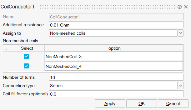
- Additional resistance: Additional resistance of the coil can be added
- Number of turns: defines the number of turns of the coil
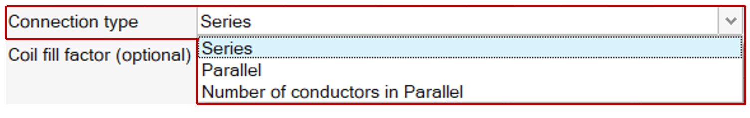
- Connection type: is used if the duplication with respect to symmetries / periodicity is enabled in the Non-Meshed Coil dialog box. This input allows to define the symmetric or periodic coils as in Series or in Parallel or with the Number of coils in parallel. For more details, please look at the section Symmetry and periodicity with Non-Meshed Coil below
- Coil fill Factor (optional): defines the optional coil fill factor value. The value must be in ]0,1]. If the coil fill factor value is entered, the coil Joule losses will be computed. For that, a Material with a resistivity value must be assigned on the Non-Meshed Coil dialog box.
Symmetry and periodicity with Non-Meshed Coil
By default, as it represents most of cases, the option Duplicate coil by symmetries and periodicity is checked.
- Creation of a composed Non-Meshed Coil by importing a file defining the path of the complete coil.
- Simulation of a device with two parts: one part partially represented because of symmetries / periodicity, and another part containing a complete coil which does not need any duplication (example: wheel speed sensor).
Once the duplication selected, the Connection type have to be defined. The connection type defines how the represented coil and all the symmetric/periodic coils are connected.
In MT3D and MAC3D, this is done in the circuit coil conductor component dialog box.
That means that if a current "I" is flowing into the represented coil, then each symmetric or periodic coil will have:
- in series: I
- in parallel: I divided by the total number of coils
in the complete deviceNote: for example, if the device has one symmetry, the current on the represented coil and in the symmetric coil will be I/2. If the device has a periodicity with a total of 6 portions, the current on each portion coil will be I/6.
- By defining a number of conductors in parallel:
Here is a table giving several examples to understand this option:
Table 2. Possible associations between periodical conductors in the example. Symmetries and Periodicites: number of conductors in series or in parallel Equivalent circuit association between conductors All in series or Number of symmetrical and periodical conductors in parallel = 1 
Number of symmetrical and periodical conductors in parallel = 2 
Number of symmetrical and periodical conductors in parallel = 3 
All in parallel or Number of symmetrical and periodical conductors in parallel = 6 
Motion
In a device, bodies can move but also Non-Meshed Coils can move.
User can define the motion for both bodies and Non-Meshed Coils in the Motion load and constraint:
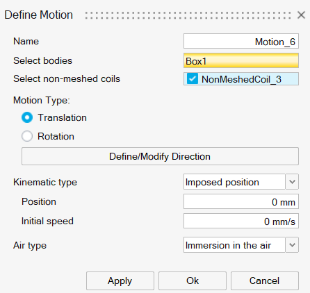
The moving Non-Meshed Coils are checked as in this example.
For more details on Motion load and constraint, please read Motion.
How to duplicate a Non-Meshed Coil
The Non-Meshed Coil duplication can be really helpful to earn coil definition time, especially for composed coil.
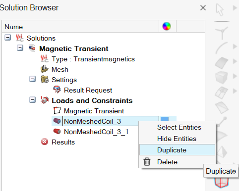
When clicking on Duplicate, a new Non-Meshed Coil entity is created with a name corresponding to the initial Non-Meshed Coil name with "_IDNumber" ("_1" or "_2" or etc.).
The common workflow with the duplication is to:
- Create a Non-Meshed Coil
- Duplicate it
- Edit the duplicated Non-Meshed Coil to modify the coordinate system for composed coils and rectangular coils or the center coordinates for circular coils
Limitations
Here are the current limitations about Non-Meshed Coils:
- No parametric on the composed Non-Meshed Coil points coordinates and curvature values
- The workflow to define a coordinate system is not optimal. Improvements are planned.
-
The Non-Meshed Coil preview needs to be improved:
- No representation of the duplicated parts of the coils with respects to symmetries and periodicity
- No dimensions display on the graphic to help the geometrical inputs entering
- No visualization of the Non-Meshed Coil preview in the post processing except while the dialog box is opened.
- Not possible to transform meshed coils (defined with bodies) to Non-Meshed Coil and vice versa