Periodicity
![]()
Introduction
Periodic boundary conditions are used when the physical geometry of interest is periodically repeating in nature. By applying the periodic boundary condition, we can reduce the model size, thereby reducing the computation time.
If your device is periodic, you can define a Periodicity.
The Periodicity allows you to create a periodicity (geometrical and physical aspects).
Periodicity conditions on boundaries
When a device has repetitive patterns, it is possible to model a fraction of the device (the basic pattern), and to impose appropriate periodicity conditions on the periodicity planes.
From a physical point of view, periodicity boundary conditions are set via the state variable (potential).
|
Even periodicity (or cyclic or periodic) |
Odd periodicity (or anti-cyclic or anti-periodic) |
|---|---|
 |

|
| Identical values of the variable on the homologous nodes | Opposite values of the variable on the homologous nodes |
Types of periodicity
- Linear periodicity
- Circular periodicity
Currently only circular periodicity is supported in 3D with the boundary conditions of cyclic(Even) or anti-cyclic(Odd). Selected periodic axis will be drawn in graphics window for visualization purpose.
Periodicity and infinite box
It is possible to combine infinite box and circular periodicity. In this case, the geometry of the infinite box (points and lines) automatically follows the periodicity attached to the study domain.
| 3D domain | |
|---|---|
| No Periodicity | Periodicity |

|

|
| Full infinite box of Z-axis cylinder type | A portion of infinite box of cylinder type following the circular periodicity around the Z-axis |
Dialog Box
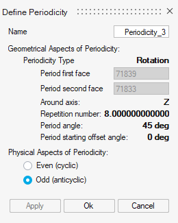
- Geometrical Aspects: select two faces is mandatory to
define the planes of periodicity.
- Periodicity typeNote: Only "Rotation" available in current release
-
Period first face: the reference plane
-
Period second face: the final plane
Note:- The order of the starting face/ending face is not important. (we take the portion which contains the represented device)
- It's mandatory to have identical geometry and mesh between these two planes. Please use the Symmetry Mesh mesh control
- The periodicity axis defined by the intersection of the planes must be one of the predefined axis: X or Y or Z.
-
"Read only" information (automatically identified after the selection of both planes faces):
-
Around axis: common axis
-
Repetition number: number of part to complete the full device
-
Period Angle: angle between the two planes
-
Period starting offset angle: angle between the reference plane and ZX plane if Z axis, XY plane if X axis, YZ plane if Y axis.
Note: This "read only" information is updated if the device is moved. -
- Periodicity type
-
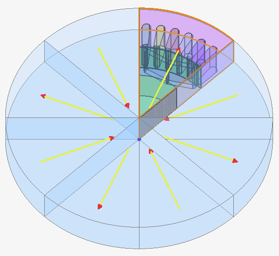
Physical Aspects
This option is necessary to define the physical definition in the non-represented portions.
The preview shows a simple illustration of the magnetic field direction in each portion depending on the chosen option, as you can see in the following image.
Even (cyclic) Odd (anticyclic) 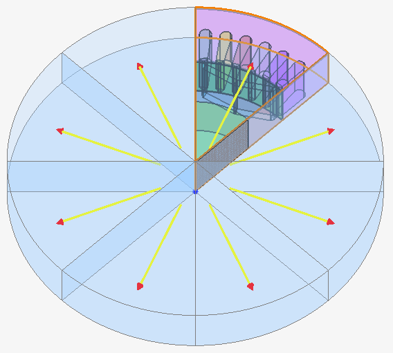
Specificity with Mesh Import
In the case of the description model is done by a Mesh Import via , (if you should add symmetry and/or periodicity) is mandatory to do on the solution bodies in order to assign the topology information on the faces. This allows then to select faces for symmetries or periodicity.
Advices
- Use the Break function to cut the device where it is necessary
- Remove the unnecessary parts
- select the bodies
- right click
- choose Delete
- Redo a Break if you need to
- Use the Symmetry Mesh mesh control to have a periodic mesh (identical mesh between the two periodicity planes)