Break - 3D Magnetic Solutions
Introduction
- cut the geometry into 2 or more. This is useful when you want to define a symmetry or a periodicity.
- create internal faces. This is useful when you have a coil and when defining the Imposed Current Coil, you have to select an internal face of the coil for current orientation.
Dialog Box
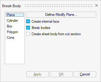
Break bodies via a Plane is selected by default.
- Create internal face to create internal faces in a
body.Note: This option only applies to surface meshed bodies.
- Break bodies to cut the body into 2 bodies.Note: For symmetry or periodicity, once the bodies have been cut, you will have to remove the bodies that are useless by right-clicking on these bodies in the graphic window and selecting the Delete contextual menu.
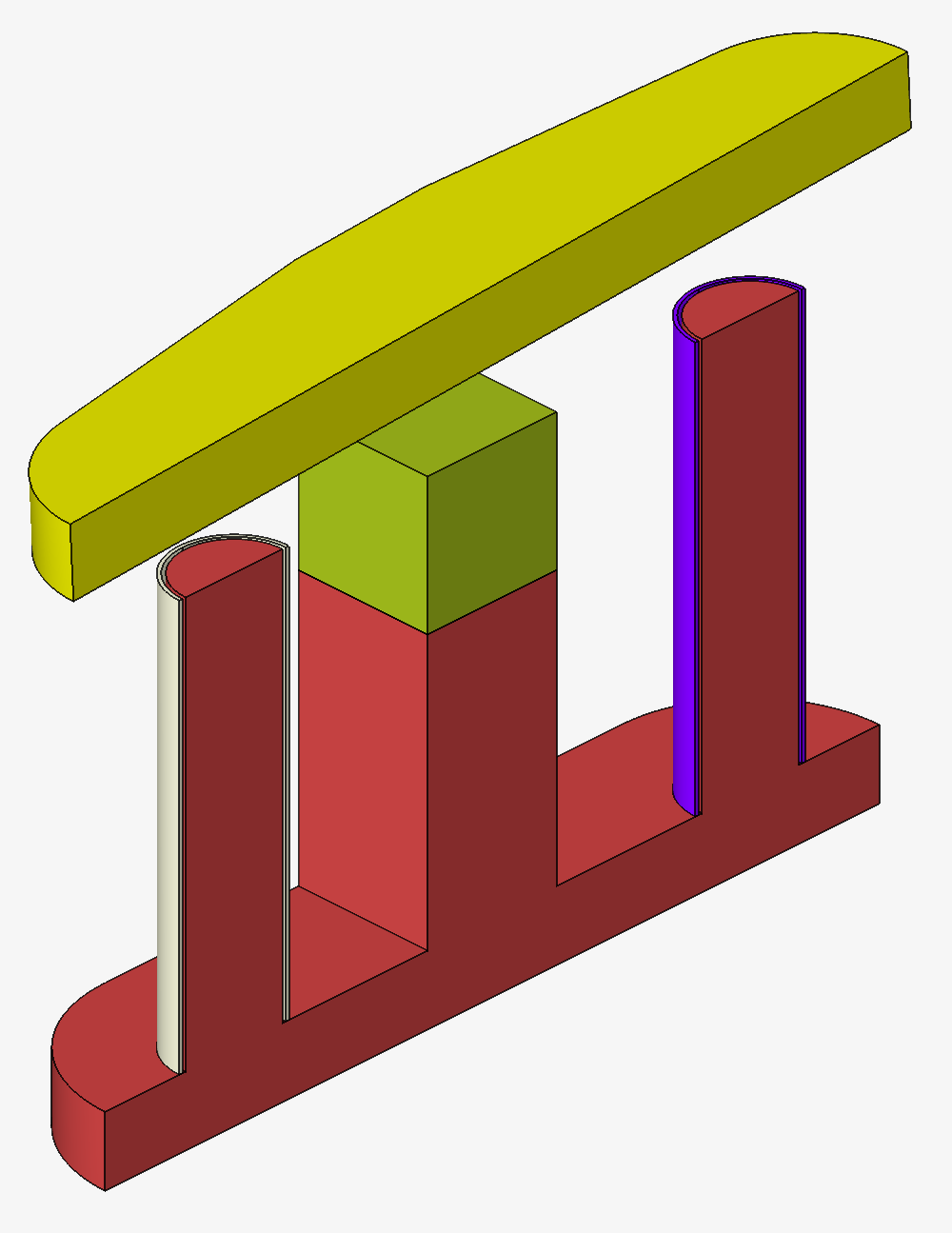
Steps for breaking bodies in the case of symmetry or periodicity
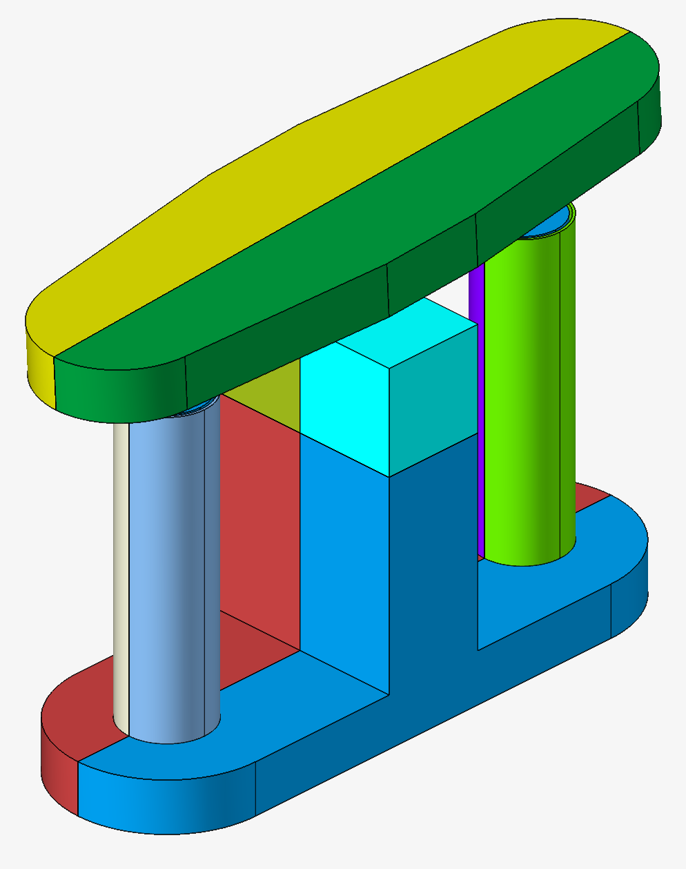
For example, in our contactor project, there is a symmetry along XZ, so we can cut the device along the XZ plane.
Thus, we model only half of the device.
- Click on the Break button in the
Geometry ribbon:

- The Break body window opens.
Keep the two first options Create internal face and Break bodies selected.
And keep Plane selected.
Click on the Define/Modify Plane button.
- The Define Plane window opens.
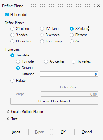
- Check the XZ plane box.
- Click on the OK button.
- Select all the bodies.
For example, you can select them in the graphic window using the mouse by drawing a rectangle surrounding the device.
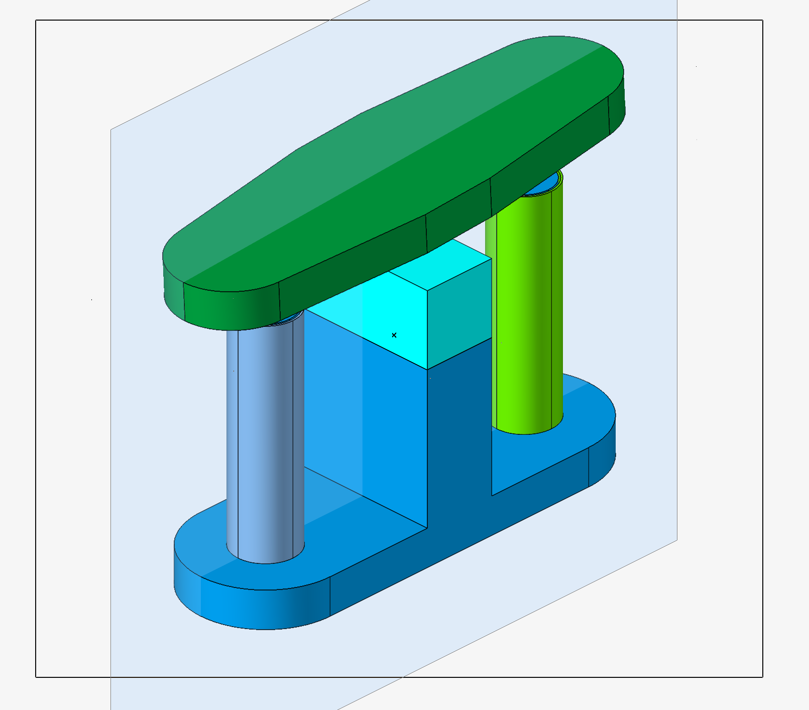
You can see that all the bodies are selected as their outline are displayed in red.
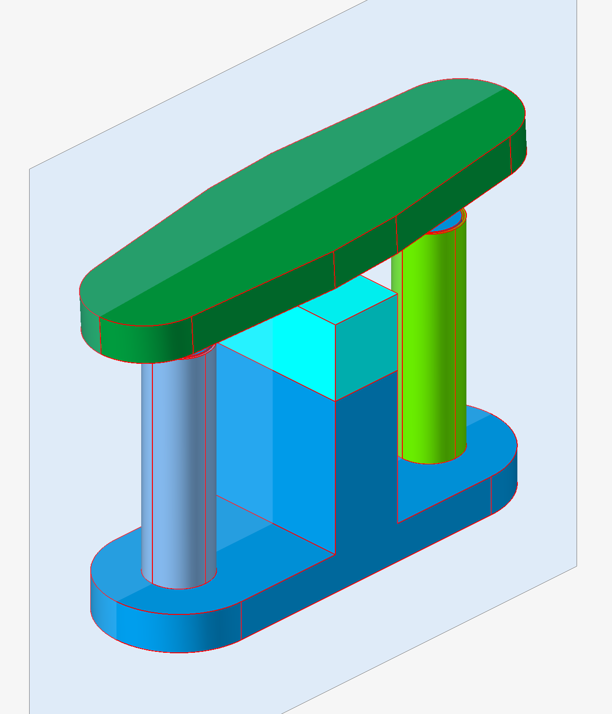
- Click on the OK button.
Each body is cut into 2 bodies.
- The Define Plane window opens.
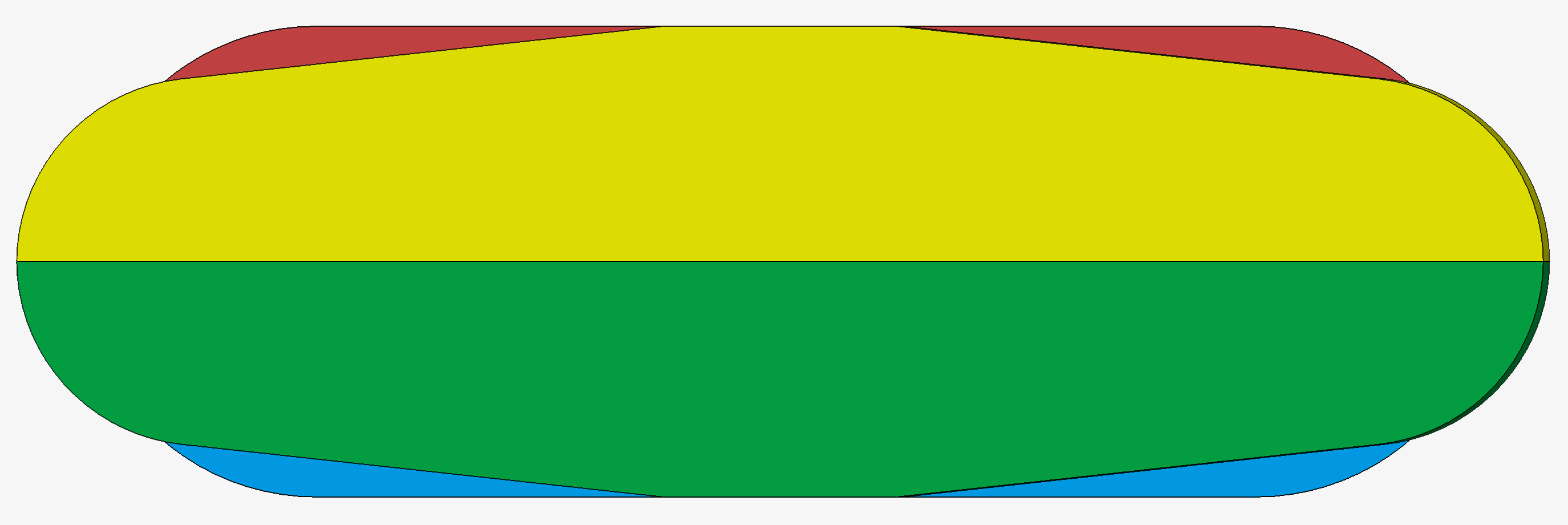
- In order to select easily the bodies to delete, you can visualize the device
in the XY plane.
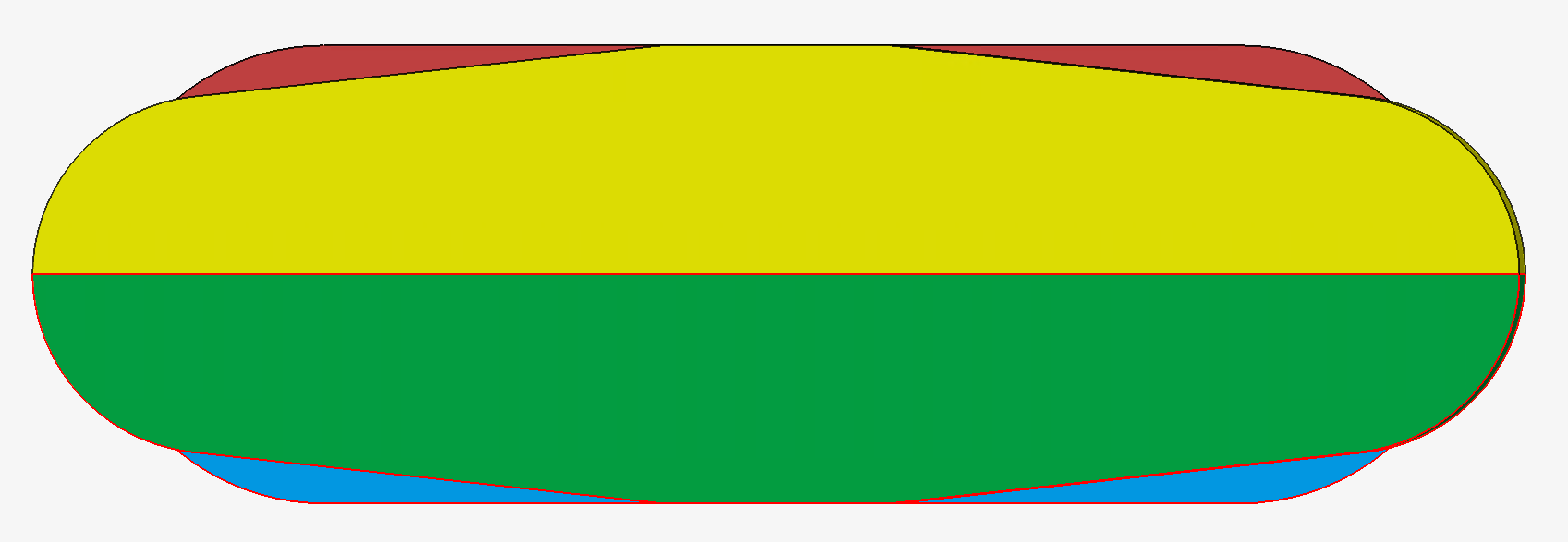
- Select the bodies that are under the XZ symmetry plane.
For example, you can select them in the graphic window using the mouse by drawing a rectangle just below the XZ symmetry plane.
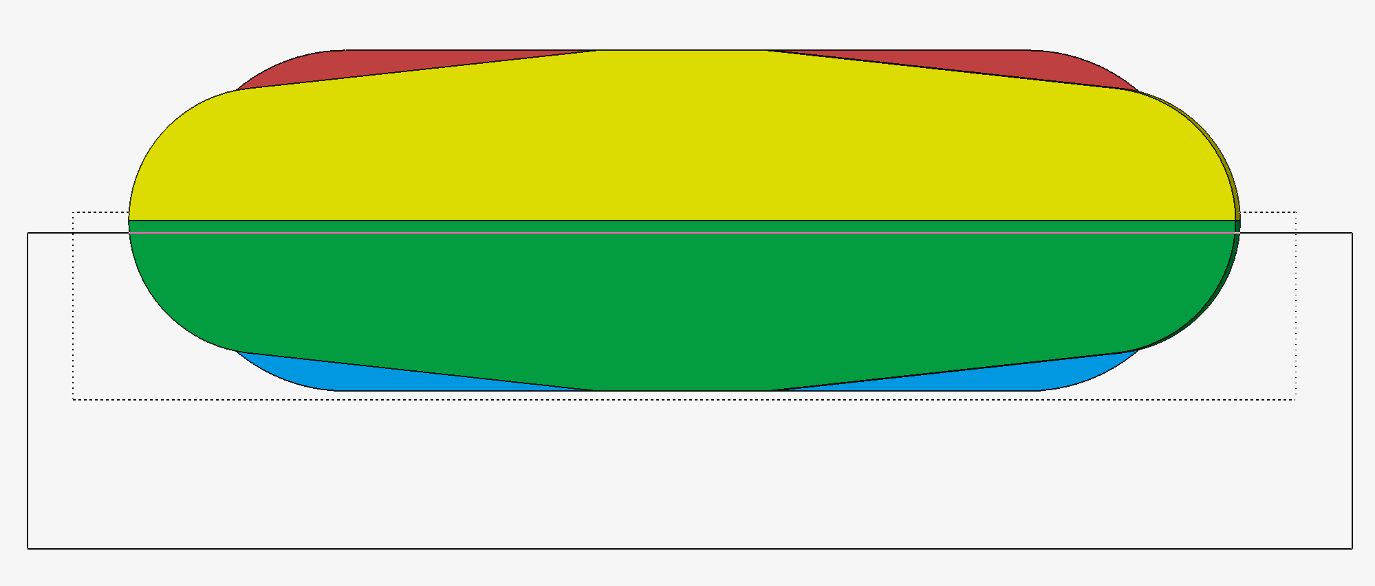
You can see that the bottom bodies are selected as their outline are displayed in red.
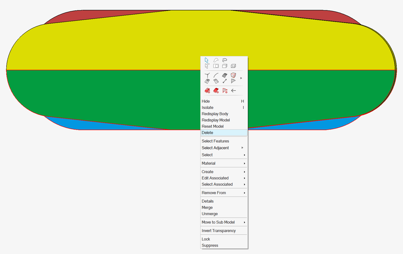
- Right-click in the graphic window and select the contextual menu:
Delete.
- Before deleting the bodies, a confirmation window opens.
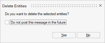
Click on the Yes button.
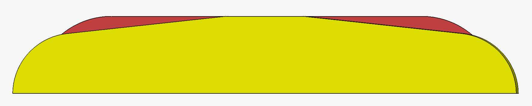
- Here is the modelled device in the initial view.
The useless bodies are deleted.
Only half of the device remains.
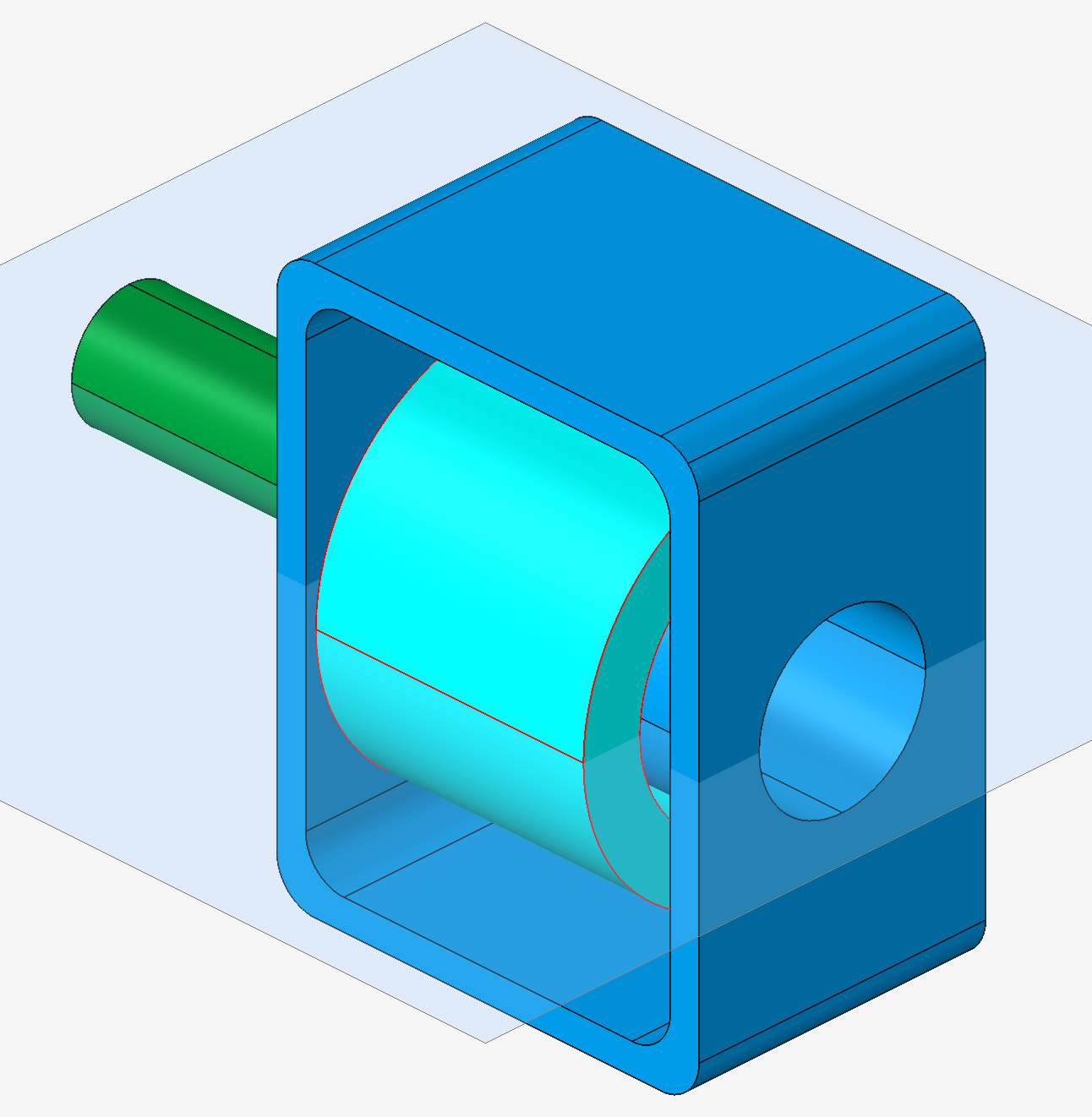
Steps for creating internal face in the case of coil
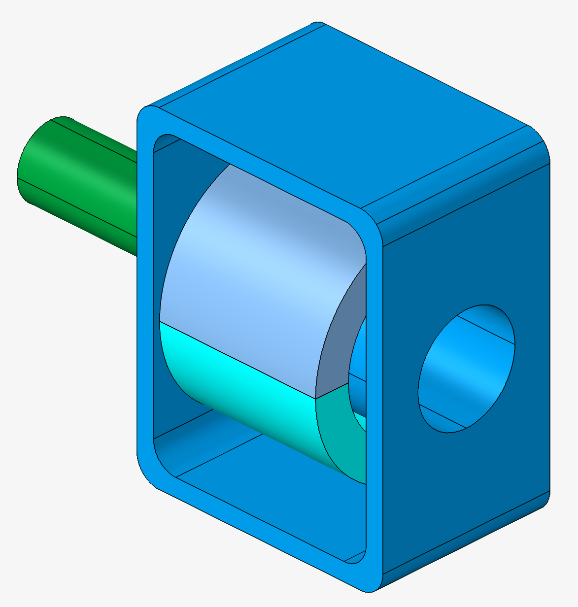
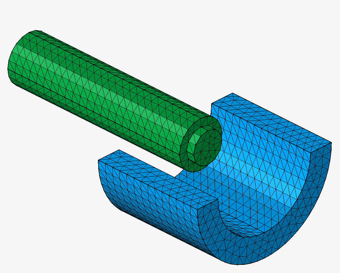
For example, in our linear actuator project simulated as a complete device (no symmetry/periodicity), for the current orientation in the coil, it is necessary to have the internal faces of the coil.
- Click on the Break button in the
Geometry ribbon:
- The Break body window opens.
Keep the two first options Create internal face and Break bodies selected.
Keep Plane selected.
Click on the Define/Modify Plane button.
- The Define Plane window opens.
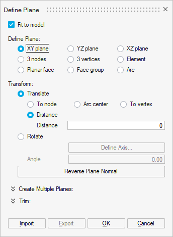
- Check the XY plane box.
- Click on the OK button.
- Select the body corresponding to the coil.
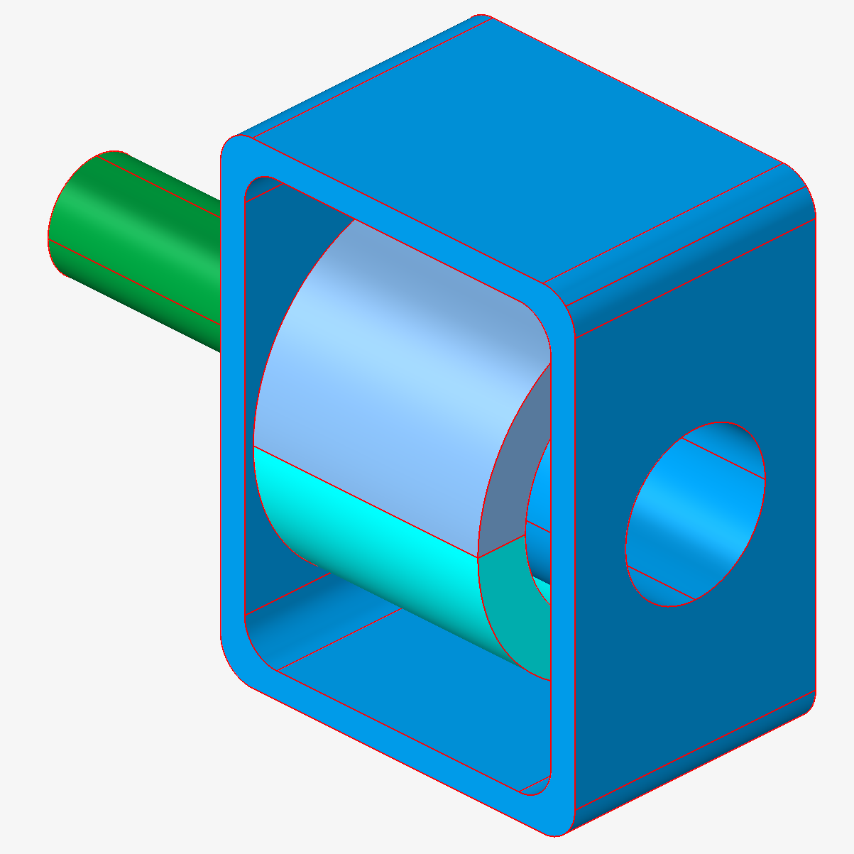
You can see that the coil body is selected as its outline is displayed in red.
- Click on the OK button.
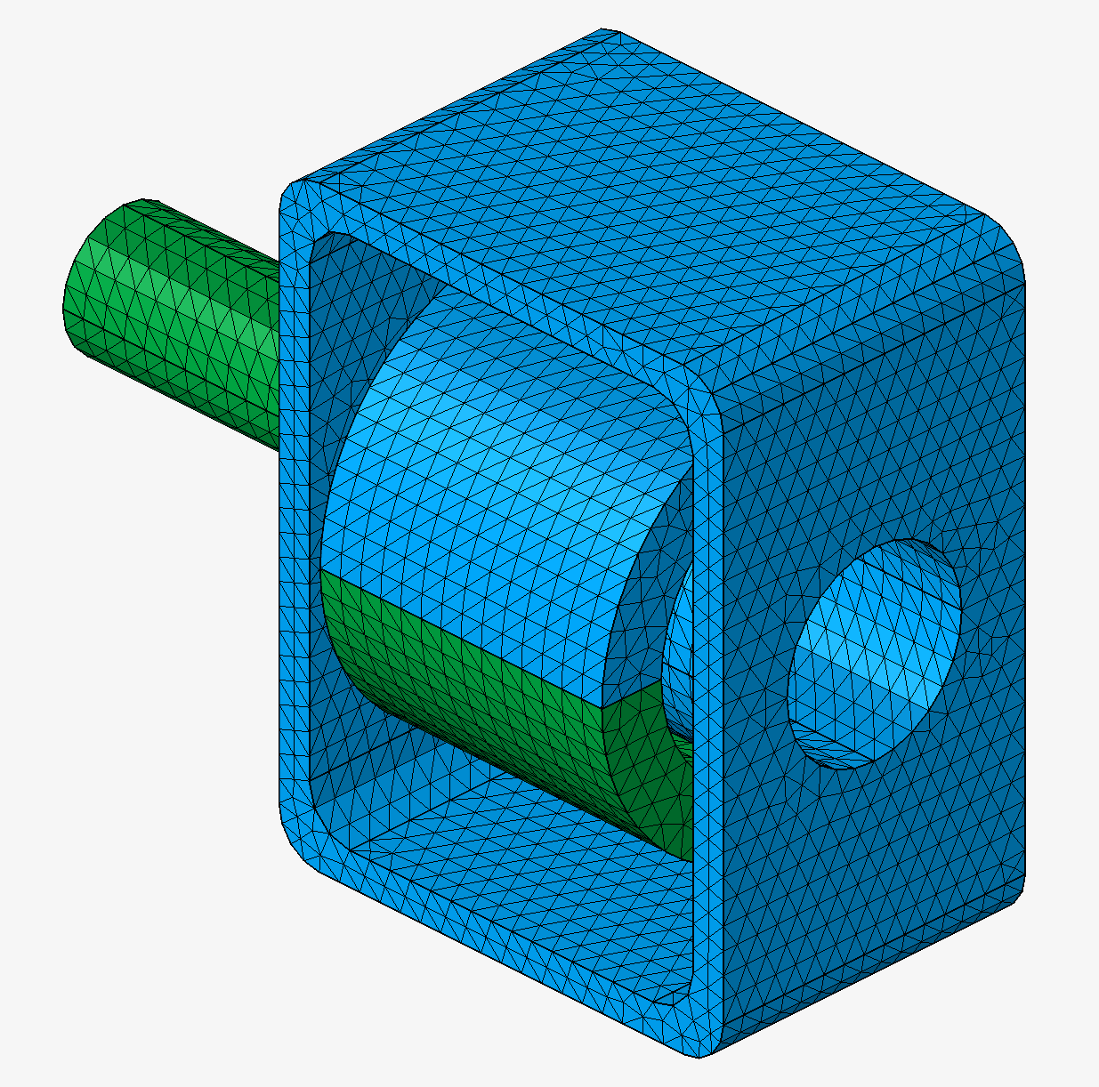
The coil body is cut into 2 bodies.
- The Define Plane window opens.
- Click on the Surface Mesh button in the
Mesh ribbon:

-
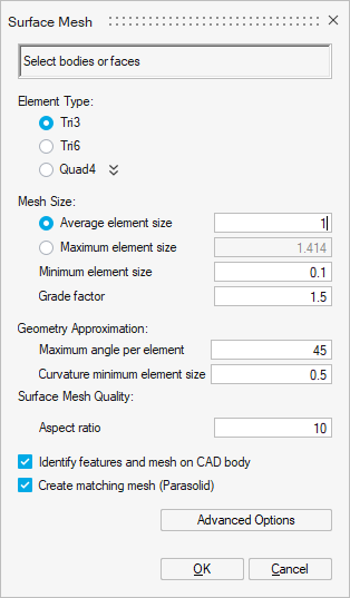
- The Surface Mesh window opens.
Fill in the information:
- Select all the bodies:
- Click on the OK button.
- The Warning window opens:
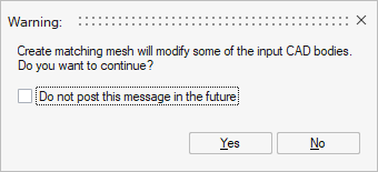
Click on the Yes button.
The surface mesh is generated.
- Select the 2 coil bodies.
Right-click and select the contextual menu: Merge.
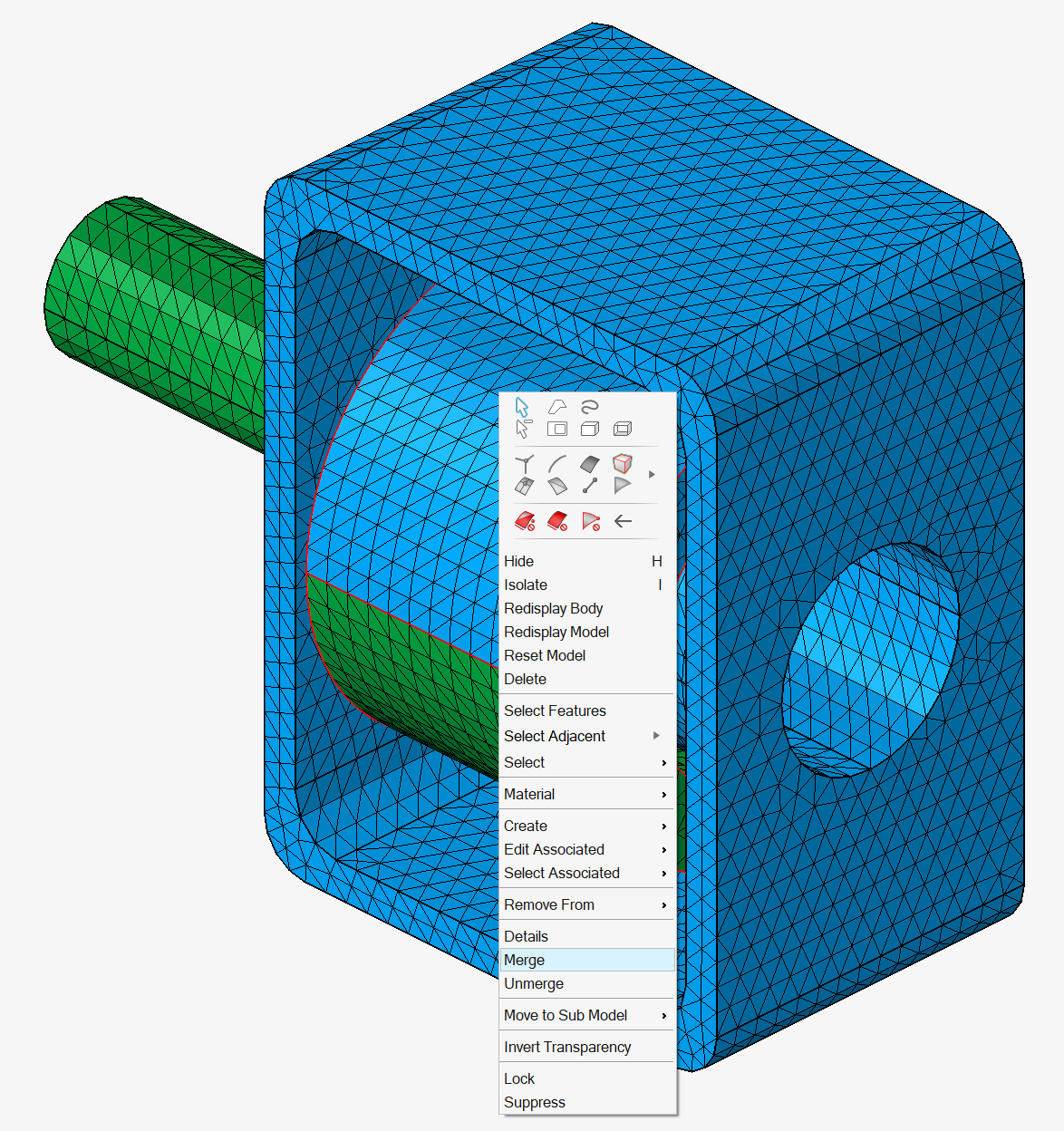
The 2 coil bodies are merged into 1 body.
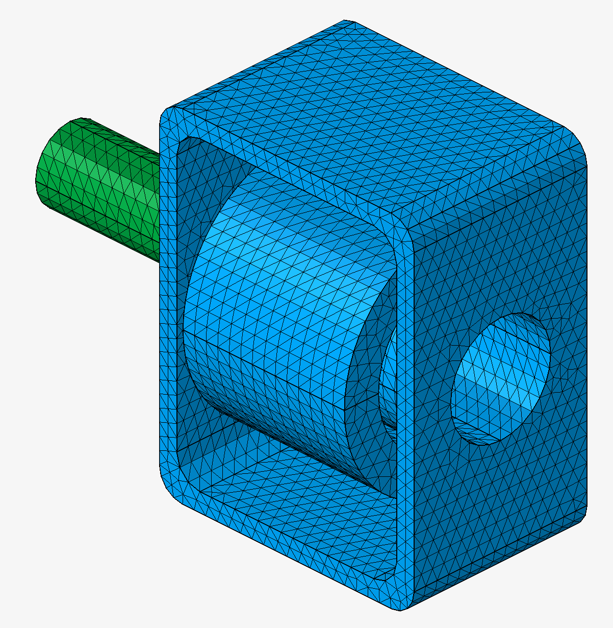
The internal faces of the coil are created.
- The Surface Mesh window opens.
Advices
It is recommended to run the Break command on CAD bodies.