Skin Effect Mesh
![]()
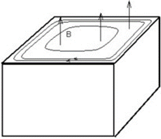
Skin Effect Phenomena
The expression of the skin effect pertains to the phenomena which occur when time varying currents are flowing through a conductor.
The AC electric currents are not uniformly distributed in the conductor cross-section but are concentrated in the external layers close to the conductor surface.
This happens when the value of either the frequency (f), or the permeability (µ), or those of the electric conductivity (σ) are high.

Skin Effect Mesh
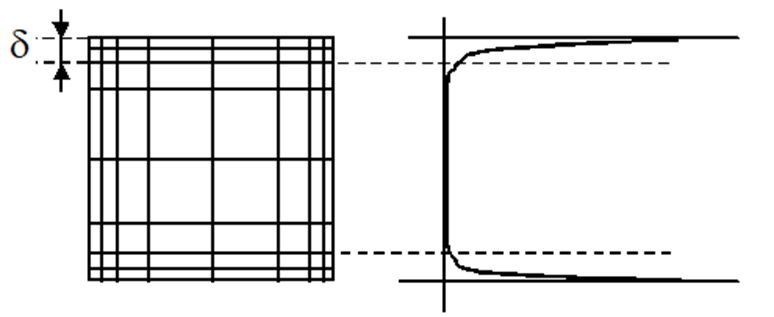
The physical quantities of the electric current or the magnetic field are exponentially decreasing in the skin depth. These fields decrease to around 37% of their original value from the surface of the material.
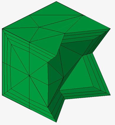
In order to have an accurate evaluation of the physical quantities in the skin depth at the surface of the conductor: it is necessary to have at least two layers of elements in the skin depth.
A mesh example of the skin depth area is presented in the figure:
Skin Depth Computation
The average value of “skin” depth in which the electric currents flow can be calculated using the following formula:

where:
f is the current frequency (Hz)
µ0 is the vacuum permeability constant = 4*π*1e-7 Kg.m.A-2.s-2
µr is the material relative permeability
ρ is the material resistivity (Ω.m)Skin Effect Mesh Features and access
There are currently 2 tools for the skin effect mesh:
- Skin effect mesh dialog:
The tool allows to create a skin effect volume mesh defined by a skin depth, number of layers, etc.
- Skin effect mesh control:

It assigns skin effect mesh settings to the selected bodies. It allows to assign different skin effect settings to the solution bodies (especially different skin depth values). The bodies with the skin effect mesh control must be meshed with Skin effect mesh tool (not Tet mesh or any other mesher). For bodies selected in the skin effect mesh dialog, if skin effect mesh controls are assigned on these bodies, the mesh controls’ inputs have higher priority
- 3D AC Magnetic
- 3D Transient Magnetic
- Parasitics Extraction
- AC Supplied Conductors
Dialog box - Skin effect mesh control
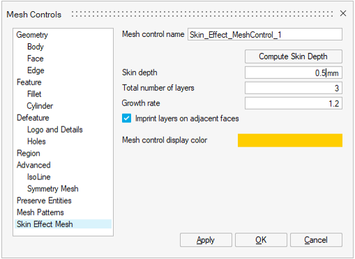
Skin effect mesh control allows to define the skin effect mesh settings for the selected bodies.
The inputs are:
- Mesh control name
- Compute Skin Depth: opens a tool to compute the skin depth value from the
physical inputs. It is possible to select a material existing in the current
model: the material data are taken to fill automatically the
Resistivity and the
Permeability
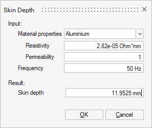
-
Skin depth value which can be computed with the Compute Skin Depth tool
- Total number of layers to define the number of elements layers in the skin depth
- Grow rate of constant type growth: This is the multiplication factor between two successive layers thicknesses (by beginning by the external layer)
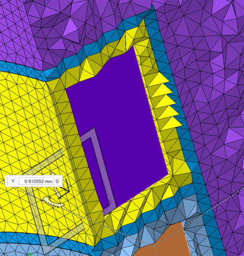
- Imprint layers on adjacent faces:
- ON: It allows mesh modification on the adjacent faces. The skin effect layers mesh will be imprinted on the adjacent faces.
- OFF: Prevents the modification of the adjacent faces.
Imprint OFF Imprint ON 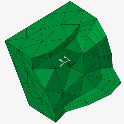
Dialog box - Skin effect dialog
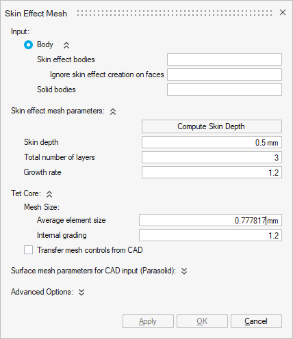
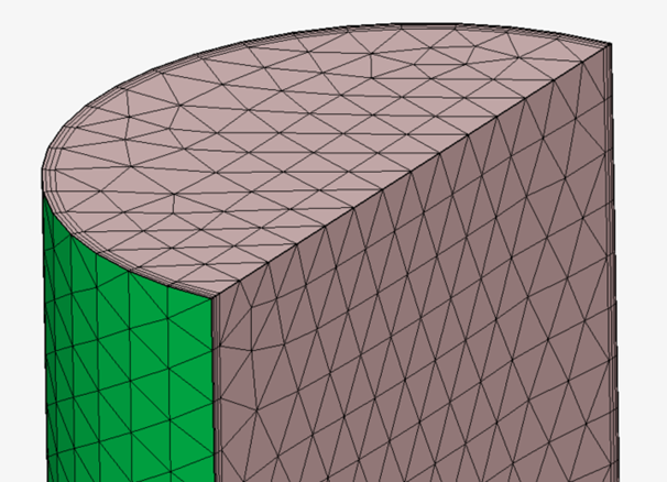
- Skin effect bodies: select the bodies where the skin effect mesh will be applied. If there are bodies already assigned to a skin effect mesh control, those bodies must be selected again.
- Ignore skin effect creation faces: select the faces from
the previously selected bodies where the skin effect mesh is not needed.
Here the faces in pink are ignored for the skin effect mesh. The skin mesh is applied only on the green face.
-
Solid bodies: select the bodies which are not concerned by the skin effect mesh. Those bodies will be meshed with the Surface mesh parameters for CAD input (Parasolid) options if they are CAD bodies, and then with the Tet Core options.
-
Skin effect mesh parameters: see the previous paragraph on the Skin effect mesh control UI.
- Tet Core: defines the Tet mesh basic settings on bodies selected in the Solid bodies field. The same settings are applied to mesh the remaining volume of the bodies selected in the skin effect mesh bodies field.
- Surface mesh parameters for CAD input (Parasolid): is available only when CAD bodies are selected. It defines the surface mesh basic settings to create the surface mesh on the CAD bodies faces.
- Advanced options:
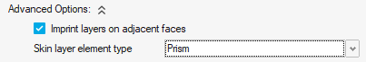
- Imprint layers on adjacent faces: See previous paragraph on the Skin effect mesh control
- Skin layer element type: by default
Prism elements layers are created for the
skin effect mesh. It allows to reduce the number of elements and
consequently the solving time comparing to the
Tetra choice. Tetra
choice can also give flat elements which can lead to bad convergence or
wrong results.Note: In Parasitics Extraction and AC Supplied Conductors solutions, by default Tetra elements is selected.
Available Workflows
Several workflows are possible with the Skin effect mesh and the Skin effect mesh control.
The 3 main workflows are:
- First workflow:
- Surface mesh all bodies
- Skin effect mesh only the bodies with skin effect mesh (no solid bodies selection)
- Tet mesh remaining bodies
This workflow allows to easily check the skin effect mesh.
It works only if there are no Quad surface elements on the bodies.
- Second workflow:
- Surface mesh all bodies
- Skin effect mesh all bodies
This workflow allows to check the surface mesh and do the volume mesh of all the bodies in once.
- Third worflow:
- Skin effect mesh all CAD bodies
This workflow allows to do the volume mesh of all the bodies in once
- Skin effect mesh all CAD bodies
Limitations
This first version of the Skin Effect Mesh has some limitations to be left in the future:
- It is advised to disable imprint in the following cases:
- If the skin effect is not applied on all the boundaries of the selected
body (some faces are ignored) and the ignored faces are shared with
other bodies of the solution
- Periodicity load and constraint exists in the solution
- If there are issues with the infinite box creation
Note: imprint option choice is taken from the skin effect mesh dialog instead of the mesh control (known issue) - If the skin effect is not applied on all the boundaries of the selected
body (some faces are ignored) and the ignored faces are shared with
other bodies of the solution
- If the skin effect mesh does not work by selecting several bodies in the skin mesh bodies, try to launch skin mesh separately on each body.
- Tet mesh is not compatible to mesh the remaining bodies if there are external quad elements (no pyramid transition done by Tet mesh) or when considering CAD bodies (no conformity management)
- If a body has a surface mesh with quad elements, skin effect mesh splits the Quad elements to transform to Tri elements