Motion

Introduction
The Motion allows you to define the motion of some bodies and eventually Non-Meshed Coils of the solution.
Dialog Box
| Imposed position | Imposed speed | Coupled load |
|---|---|---|
 |
 |
 |
- Select bodies which are moving. At least, one body must be selected.
- Select non-meshed coils which are moving (optional).
Note: If the solution does not contain any Non-Meshed Coil, this input is not shown in the Motion dialog box.
-
Motion Type: Two choices are proposed:
- Translation
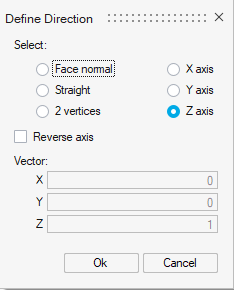
Translation direction has to be chosen through Define/Modify Direction button:
- Rotation
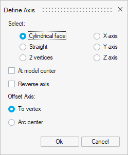
Rotation axis has to be chosen through Define/Modify Axis button:
- Translation
- Air type:
Two choices are proposed, available for both Translation and Rotation:
- Immersion in the air
This air type is chosen when the moving bodies are immersed into a large air volume.
The following example illustrates it:
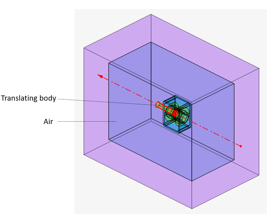
It is mostly used for translating motion.
- Sliding airgap
This air type is chosen when the moving bodies are sliding with respect to the fixed part. The sliding surface is located inside the airgap and separates the airgap into two bodies: moving airgap and fixed airgap.
The following example illustrates it: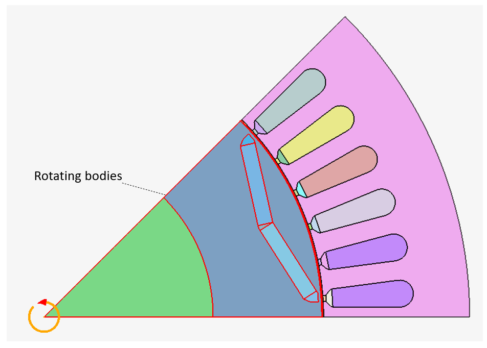
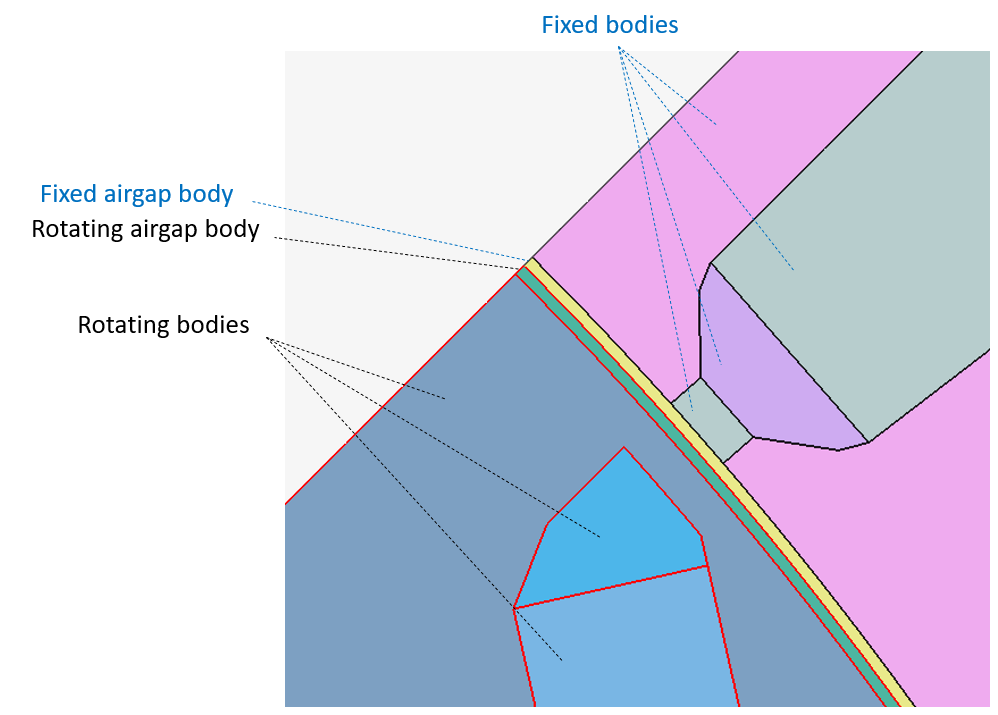
Sliding airgap is mostly used for rotating motion, especially for motors.
- Immersion in the air
- Kinematic type:
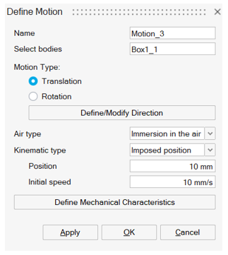
- Imposed position: The position of the selected bodies and non-meshed coils is imposed during the simulation with Position value. The Initial speed value is also entered.
- Imposed speed: The speed of the selected bodies and non-meshed coils is imposed during the simulation with Speed value. The Initial position value is also entered.
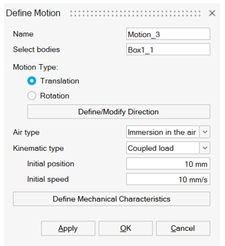
- Coupled load: The solving is done with the magneto-mechanical coupling. The inputs are the Initial position and the Initial speed.
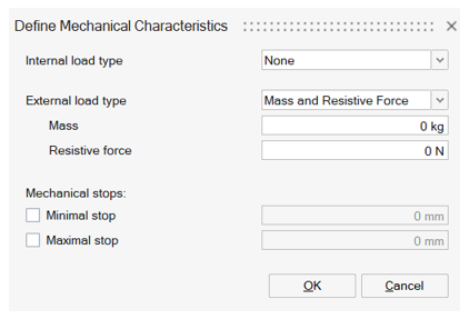
- Define Mechanical Characteristics:
This button is available for the 3 kinematic types: Imposed position, Imposed speed, and Coupled load.
The button opens another dialog box to define
- the Internal and External load
types
- for the Translation motion type,
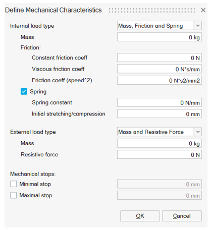
there are 3 internal/external load types:
- Mass and Resistive Force i.e.
define the
- Mass
- Resistive force
- Mass, Friction and Spring
i.e. define the
- Mass
- Friction: Constant friction coeff, Viscous friction coeff, Friction coeff (speed^2)
- Spring (optional): Spring constant, Initial stretching/compression
- NoneNote: None is available only for Imposed position or Imposed speed kinematic type.
- Mass and Resistive Force i.e.
define the
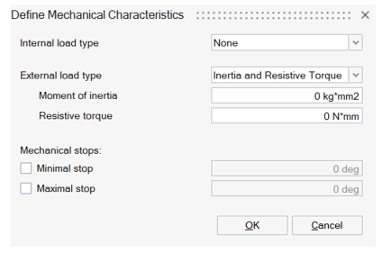
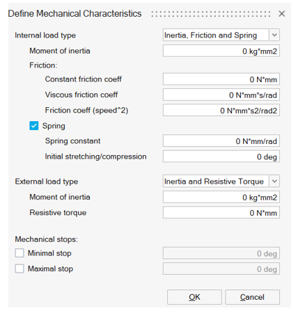
- for the Rotation motion type, there
are 3 internal/external load types:
- Inertia and Resistive Torque
i.e. define the
- Moment of inertia
- Resistive torque
- Inertia, Friction and Spring
i.e. define the
- Moment of inertia
- Friction: Constant friction coeff, Viscous friction coeff, Friction coeff (speed^2)
- Spring (optional): Spring constant, Initial stretching/compression
- NoneNote: None is available only for Imposed position or Imposed speed kinematic type.
- Inertia and Resistive Torque
i.e. define the
- for the Translation motion type,
there are 3 internal/external load types:
- the Mechanical stops
The mechanical stops allow to block the minimal and/or the maximal position with the selected value.
Optionally define the Minimal stop and the Maximal stop.Note: The Mechanical stops are available only for Imposed speed or Coupled load kinematic type.Imposed position Imposed speed Coupled load Translation type motion 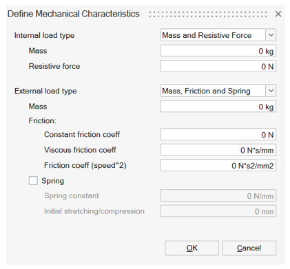
Rotation type motion 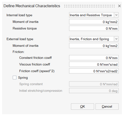
- the Internal and External load
types
Motion parameters for solving
The solving parameters are defined in the solution dialog box.
It is possible to pilot either Time or Angular position or Linear position. Please refer to Transient Magnetic solution for more information on the solution dialog box.
| Control Parameter / Motion type | Translation | Rotation |
|---|---|---|
| Time | All types | All types |
| Angular Position | Not compatible | Imposed Speed |
| Linear Position | Imposed Speed | Not compatible |
The compatibility is checked: Error messages are displayed if an incompatible configuration has been selected.
Steps : Example of Translation Motion on a linear actuator
-
Click on the Motion button in analysis ribbon:
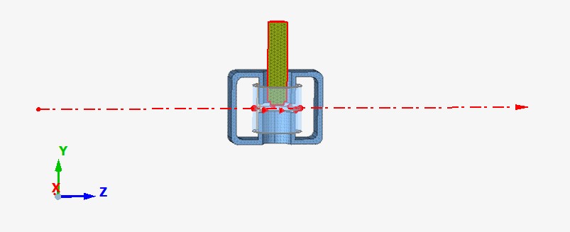
→ A default direction of the translation with an arrow on Z is visible at Motion box opening. This will be changed in following steps.
- Select bodies which are moving. In this case, the
body highlighted in red in the upper image.
→ The selected bodies are highlighted, and the corresponding field in the dialog box is filled with selected bodies names.
- Select non-meshed coils: In this case, the existing non-meshed coil is not moving so it is not selected
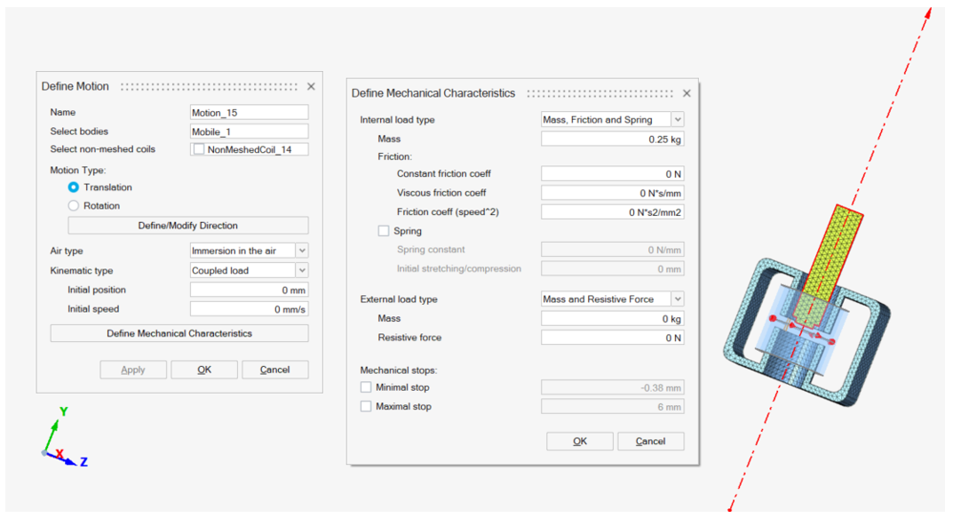
- Select Motion type as Translation
- Open Define/Modify Direction. Select Y axis and
OK.
→ The preview of the translation direction is correctly updated.
- Check that Air type is set to Immersion in the air (default choice for Translation).
- Define the Kinematic type for example as Coupled load (magneto-mechanical coupling).
- Open Define Mechanical Characteristics. Define Internal load type as Mass, Friction and Spring. And enter the Mass as 0.25Kg.
- Click on Ok.
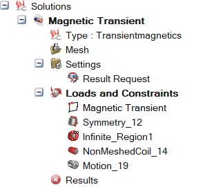
→ The Motion is created and appears in the Model Browser of Solution tab in the node Loads and Constraints
- The solving must be piloted. This has to be done in the
Solution box, before or after the Motion creation. In the case it is done
after the Motion creation:
-
Double click on the Solution in the Solution Browser to edit the solution and open the dialog box:
→ The following dialog box is opened: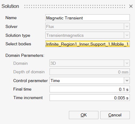
- In this case, as we defined the Motion as Coupled load, the Control parameter is necessarily Time.
- The Final time and Time increment are entered with the values shown in the previous image
- Click on OK
→ The project is ready to be solved.
-
Advices
- In the use case of Immersion in the air air type (mostly for Translation use case), it is advised to reduce as much as possible the surrounding air body size. In fact, as this body is remeshed in Flux at each moving step, reducing its size will reduce memory storage requirements and solving time.
- In the use case of Sliding airgap air type (mostly
for Rotation use case), it is important that the
areas of face to face surface elements be approximately the same for any
rotating angle. This is illustrated in the figures below.
Recommended meshing 

Non-recommended meshing (inhomogeneous density of nodes along the two circumferences) 

Limitations
- In this version: Only one motion entity can be created in a solution.
- In this version: In the use case of Immersion in the air air type (mostly for Translation use case), the contact between the fixed device bodies (except surrounding air body) and moving bodies is forbidden. In consequence, user must choose carefully the motion parameters values in the solution box to keep a gap between the moving bodies and the fixed bodies for all solving steps.