About Representations
Different methods for modeling a part are called representations.
Parts can be modeled with different element configurations or mesh densities based on what type of analysis you are running.
You can have multiple representations of a part accessible from your model; these representations can be loaded interchangeably. Each representation has a name and type assigned. Representations can either be created through interactive modeling and saving a representation or created automatically through BatchMesher.
The representation types that can be automatically created through BatchMesher are: Midsurface, CFD 2D Mesh, Hexa Bounding Box, Hexa Thin Solid, Midmesh, Rigid Body Mesh, Shell, Tetra, and Custom.
After creation, you can opt to immediately load the representations into the session. The initial output can be further modified to improve element quality as necessary, and the representation is saved again.
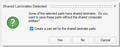
If you select Yes, parts which contain shared laminates will be saved but the shared composite entities will be skipped. If you select No, shared laminate parts will not be saved. In either case, you can choose to create a part set for these parts as well.
When loading a representation, curves, features, laminates, plies, shapes, tables, sequences, and systems will not merge with entities that already exist in-session, creating duplicates. Unloading does not take place for curves, systems, and their collectors. For tables it does, but only when they are referenced by plies.
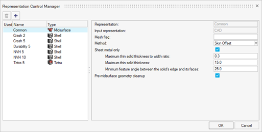
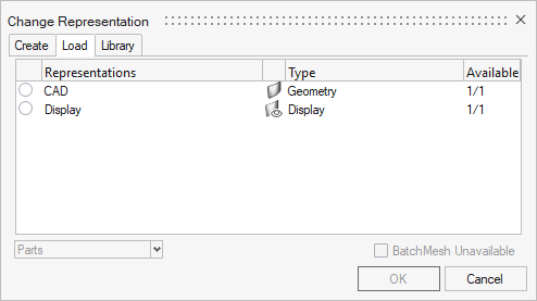
The various types of representations are shown in the Representation Control Manager. To launch the dialog, click the Controls icon on the Assembly ribbon, or right-click anywhere in the Part Browser and select in the context menu (see Define Representation Controls).
| Name | Type |
|---|---|
| CAD | Geometry |
| Common | Midsurface |
| Display | Display |
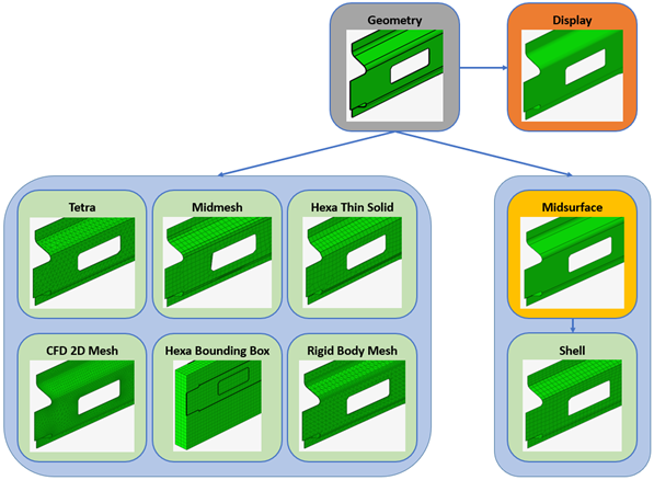
- CAD
- Solid geometry representation that comes from the imported geometry file. It is the input for many downstream representations.
- Display
- Lightweight visualization of the CAD representation used for review. See Display Representation for more information.
- Common
- Create midsurfaced geometry. It is derived from the CAD representation and forms a single, common input for creating any subsequent shell mesh representations. This common input enables one-time creation and clean-up steps for all future shell representations.
- Shell
- Create a 2D mesh on the midsurface of the selected parts. Common representation is taken as input and utilizes BatchMesher's param and criteria files.
- Tetra
- Mesh the volume enclosed by solids using first or second order tetrahedral elements. CAD representation is taken as input.
- Midmesh
- For parts such as castings, rather than creating a midsurface representations, you can directly extract the midmesh if desired. CAD representation is taken as input.
- CFD 2D Mesh
- Mesh the boundary surface of parts. CAD representation is taken as input.
- Rigid Body Mesh
- Create a mesh to represent the topology of a rigid object. The rigid body mesh focuses on accurately modeling the shape of a part rather than on producing a high-quality mesh. CAD representation is taken as input.
- Hexa Bounding Box
- Create a hexa-meshed bounding box representation for the selected parts. Regardless of the input, a cuboid mesh of hexahedral elements is generated using the maximum dimensions of the part. CAD representation is taken as input.
- Hexa Thin Solid
- Create 3D mesh on thin solids. The mesh is created by first generating a 2D mesh on an auto-selected set of source faces, then extruding this mesh to generate solid hexa or wedge elements. CAD representation is taken as input.
- Custom
- Create a customized part representation using a tcl script. Optionally, it allows selection of a param and criteria file in order to utilize BatchMesher's meshing capability in addition to the provided script.
Display Representation
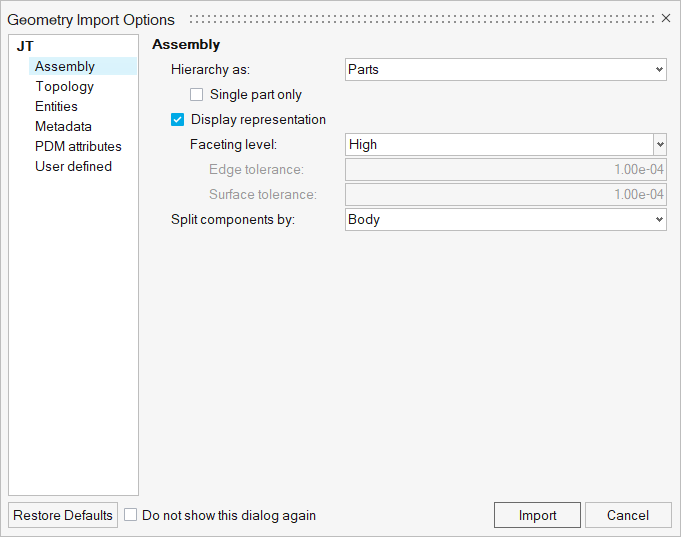
The main purpose of the display representation is to provide a lightweight version of geometry that allows fast loading of large assemblies, leading to significant time savings. This is a convenient way to perform initial inspections of the model. You can select the Display representation option when importing Geometry files (Figure 4) and after importing a BOM file (Figure 5).
Supported geometry file formats are: Acis, CATIA, CatiaV6, Creo, Inspire, Inventor, JT, Rhino, NX native, NX third party, Parasolid, SLDPRT/SLDASM, STEP, VDAFS.
Respective import options can be accessed from the Part Browser using the context menu .
- Choose Low to set the faceting level to the lowest level.
- Choose Medium to set faceting level to its normal (default option).
- Choose High to set the faceting level to its maximum.
- Choose Custom to set the edge and surface tolerance manually (default: 1e-04).
Common Representation
The common representation consists of midsurfaced geometry. It is derived from the CAD representation and forms a single, common input for creating any subsequent discipline-specific shell mesh representations. This common input enables one-time creation and cleanup steps for all future shell representations.
During creation, the CAD is sent to the BatchMesher for midsurface extraction. Upon completion, the result is saved and you can opt to immediately load the representation into the session.
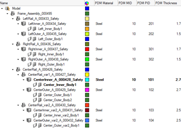
When the geometry has areas with varying thickness, BatchMesher will automatically detect and organize the surfaces into components based on their thickness. Then, a property will be assigned to each of the newly created components with the thickness value. HyperMesh entities are generated from the PDM metadata, if available. The PDM PID is assigned to the component and property IDs, the PDM MID and PDM Material are assigned to the material, and the PDM Thickness is assigned to the thickness attribute of the property. If the PDM Thickness is blank, the CAD thickness calculated during the midsurface operation is automatically assigned to the thickness attribute of the property.
By default, the midsurface algorithm "skin" is used. The CAD representation does not need to be loaded into the session to generate the common representation, since it is sent directly to the BatchMesher for processing.
When you create a shell representation, the Common representation is automatically sent to the BatchMesher for processing. The common representation does not need to be loaded in the session to generate shell representations. In case it does not exist, it is automatically generated by extracting the midsurface from the CAD representation.