FE Geometry
FE geometry is topology on top of mesh, meaning CAD and mesh exist as a single entity. The purpose of FE geometry is to add vertices, edges, surfaces, and solids on FE models which have no CAD geometry.
Tools and workflows operate similarly on CAD as they do with FE. With FE geometry, mesh selections are made easier as they are topology-based.
FE geometry can be used for 1D and 2D elements. It is recommended to use FE geometry where there is no associated CAD.
FE Geometry Creation
FE geometry creation in HyperMesh tools is controlled from .
When the create mode is set to CAD geometry, all points, lines, surfaces, and solids created will be CAD geometry.
When the create mode is set to FE geometry, all points, lines, surfaces, and solids created will be FE geometry.
Midmesh default extraction output will be FE geometry only.
Creation Rules Applied in Tools and Workflows
- For CAD geometry inputs, expected output is CAD geometry.Ruled surface creation from two CAD edges gives CAD geometry surface.
Figure 1. 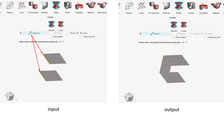
- For FE geometry inputs, expected output is FE geometry.Ruled surface creation from two FE geometry edges gives FE geometry surface.
Figure 2. 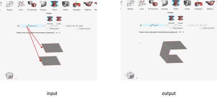
- For mixed inputs (CAD geometry + FE geometry), the expected output is defined by
the option in Preferences.The same is true for the following:
- Ruled surface creation from mixed selection (CAD edge and FE geometry edge)
- Connectivity within or across component
- Orphan nodes locations
- Structural nodes (not associated) selection
CAD edge/CAD line selection results in CAD surface.
FE edge/FE line selection results in FE surface.
Figure 3. 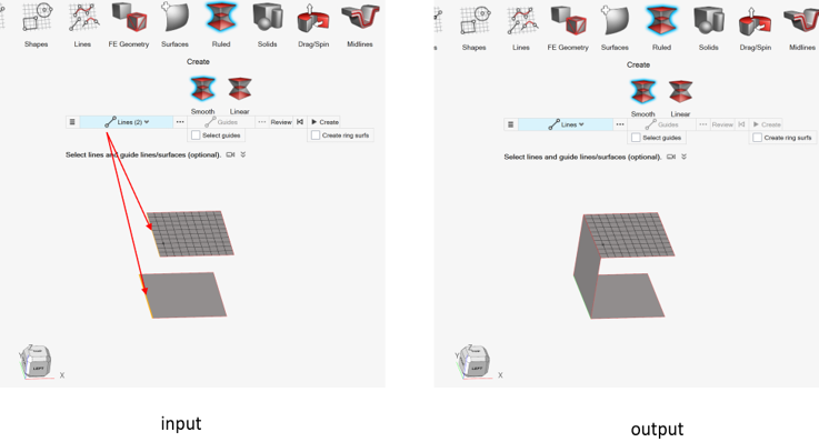
FE Topology Revision
FE topology revision in HyperMesh tools is controlled from .
Any of the three methods can be used for FE topology revision.
- Keep mesh
- Keep existing mesh on FE topology revision.
- Remesh
- Remesh surrounding mesh on FE topology revision.
- Rebuild
- Rebuild surrounding mesh on FE topology revision.
- Number of layers
- Define the zone to be remeshed or rebuild on topology revision.
Convert to and Update FE Geometry
Use the FE Geometry tools to convert elements or CAD surfaces into FE geometry, or update existing FE geometry.
-
From the Topology ribbon, click the FE
Geometry tool.
Figure 4. 
-
Select an option from the secondary ribbon.
Option Description From CAD 
Select CAD geometry with associated elements to convert. From Elements 
Select elements that are not associated with geometry to convert. Click
 on the guide bar
to define options.
on the guide bar
to define options.- Create at features
-
- Simple
- Fast method of identifying features based solely on the angle between normals of adjacent elements. Based on this, the surface is created.
- Connected
- Seeks to avoid any "orphan" or non-closed feature lines. It includes a more rigorous check to combine small areas and avoid creating features that end abruptly or do not connect to any other features while creating surfaces.
- Curvature Based
- Uses curvature analysis to detect and trace surface features by evaluating how sharply the model bends. Areas with low curvature are treated as flat, while high-curvature regions are examined using principal directions to generate smooth, meaningful lines. User-defined parameters help refine the detection in both vertical and horizontal directions, allowing greater control over feature detail and flow.
- Example shown in Figure 5.
Figure 5. 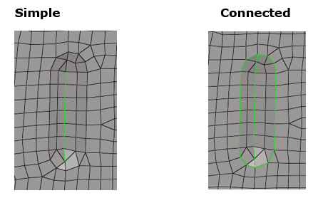
- Edge feature angle
- Used in all methods.
- Vertex feature angle
- Only used in Simple and Connected.
- Maintain connectivity of the input surfaces to
any attached surfaces.
Figure 6. 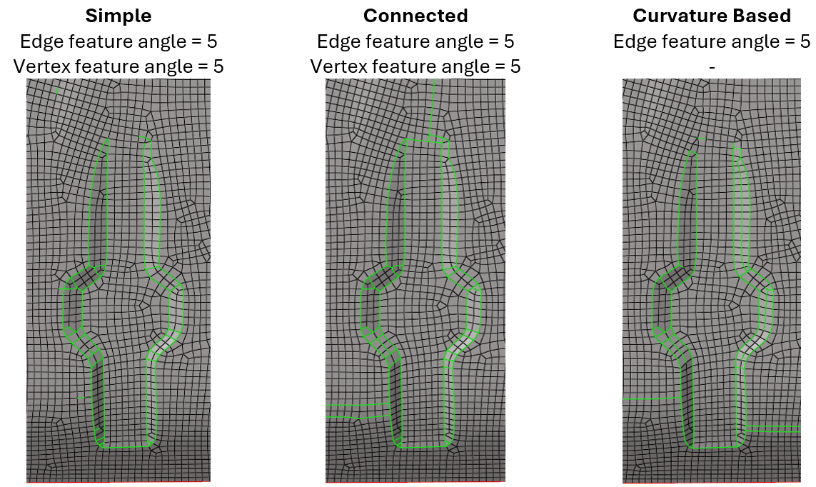
Figure 7. 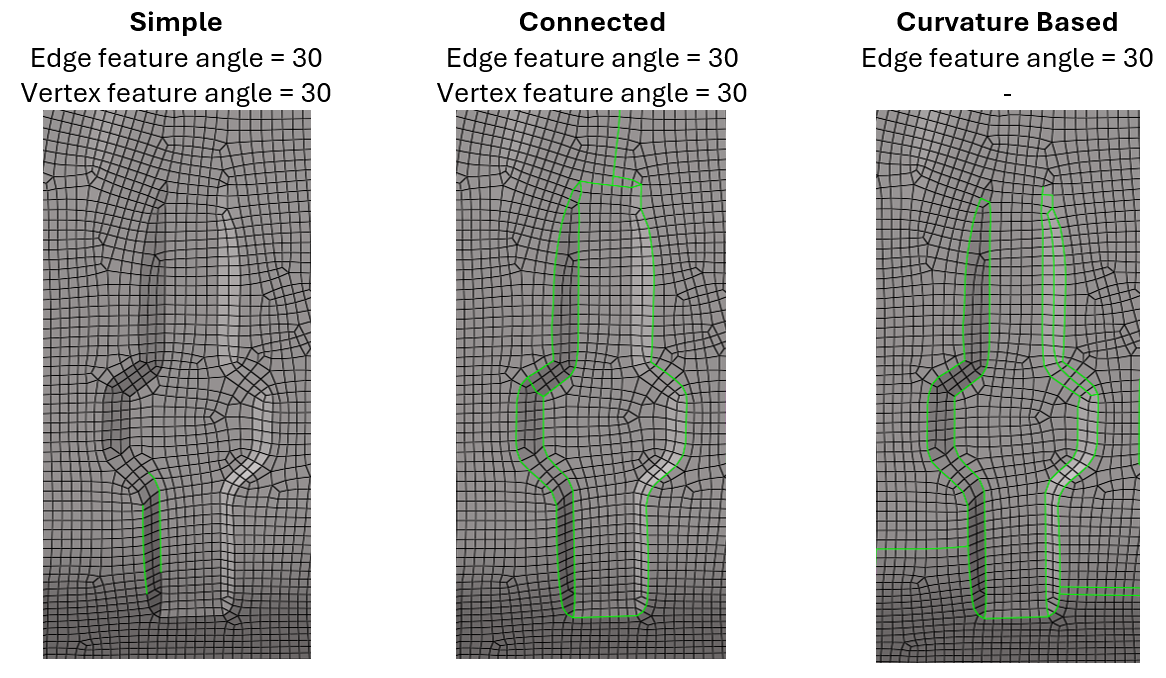
- Vertical filter
- Only used in Curvature Based.
- Parallel filter
- Only used in Curvature Based.
- Range 0 – 1: Reduce to get finer lines.
Figure 8. 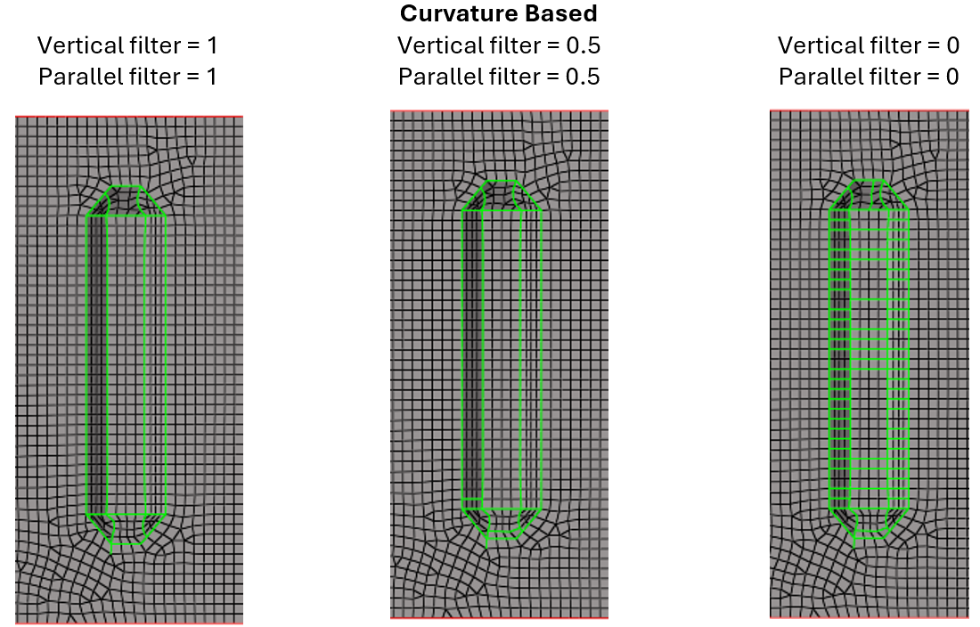
- Allow open features
- Only used in Simple and Connected.
- Orphan feature edges can be created with this
option, as shown in Figure 9 below by the Simple example.
Figure 9. 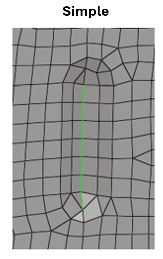
- Create at component boundaries
- The feature edge separating the component boundary is created while creating different surfaces.
- Create solids
- Orphan elements forming an enclosed volume are converted into a solid.
- Create at 1D elements
- Feature edges are created at 1D elements.
Update 
Select existing FE geometry to update. Surfaces and elements can be selected, and, using the options above, new FE geometry can be created.
In addition to the "From Elements" options, click
on the guide bar
to define:- Remove existing features
- Before creating FE geometry, existing features can be removed.
- Create at selection boundaries
- Feature edges are created considering element selection.
Functionalities Without FE Geometry Support
Below is a list of functionalities not yet supporting FE geometry in HyperMesh 2026
Geometry
- Extend: Stitch at target using “Auto trim intersecting surface” option is not supported.
- Offset
- Drag/Spin: Preview of FE geometry solid is not available.
- Midlines: FE geometry solid is not supported
- Midsurfaces
- Split > Lines: FE geometry line split is not supported.
- Split > Surfaces: Extend trimmer is not supported for FE geometry.
- Split > Surfaces: “Trim both” is not supported for mixed selection.
- Split > Surfaces: “Self-intersecting surfaces” is not supported for mixed selection.
- Split > Surfaces: Split CAD using FE geometry is not supported.
- Split > Plane: FE geometry line split is not supported.
- Split > Plane: Review is not available for FE geometry solid split.
- Stitch: Mixed selection is not supported.
- Suppress: Mixed selection is not supported.
- Unsuppress
- Fillets
- Boolean
- Plug
- Defeature > Cuts, Small Features, Logos, Fillets and Batch
- Preserve Edges
Mesh
- Batchmesh and Rigid body meshing does not support FE geometry as input.
- Assign plot contour is not supported for FE geometry elements in the Check elements (F10) 1D & 2D panel.
- Tetra: FE geometry solid elements creation is not supported.
- Hex: FE geometry solid elements creation is not supported.
- Solid Map: FE geometry solid elements creation is not supported
- Thin Solids: FE geometry solid elements creation is not supported.
Elements
- Refine > Auto quads and Box