Renumber Entities
Use the Renumber tool to review and organize the IDs of model entities.
Organizing entity IDs can facilitate easier post-processing and model management. This tool can renumber entities into a different range, offset the IDs of selected entities by a specified amount, and/or renumber entities in a particular order.
-
From the Assembly ribbon, click the
Renumber tool.
Figure 1. 
- Choose either the Renumber or the Offset method from the drop-down on the guide bar.
-
Select the entities to be renumbered.
- Alternatively, choose All from the selector drop-down menu to renumber all entities of every type in the model at the same time.
- Use the Alt shortcut key to quickly make selections by path.
-
Input the new starting ID and/or offset as appropriate.
By default, entities will be renumbered to the next available ID if the starting ID is already in use. The Overwrite existing IDs option will force renumbering into the specified range and automatically renumber any conflicting entities above the highest ID used in the model.
-
On the guide bar, click one of the following:
 - Apply and stay in the tool
 - Apply and close the tool
 - Exit the tool without applying
Use the Maintain selection option to perform iterative renumbering actions on the same selection.
Spatial Renumbering
Renumber elements and nodes based on spatial sorting.
- From the Assembly ribbon, click the arrow next to the Renumber tool, then select Spatial Renumber.
- Select a sorting schema from the drop-down on the guide bar.
- Select a list of nodes or elements to renumber.
-
Use the microdialog to define relevant options.
Option Description Spatial - Click
 and select a
system.
and select a
system.The global system may be used.
- Define the ordered list of axes to consider to sort the
selection (primary/secondary/tertiary axes).
Arrows will show the starting location and directions for renumbering.
- Define the start ID.
- Define a tolerance and ID increment for each axis.
The ID schema is continuous across directions.
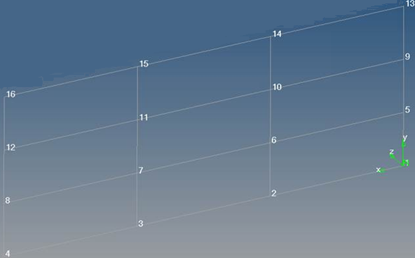
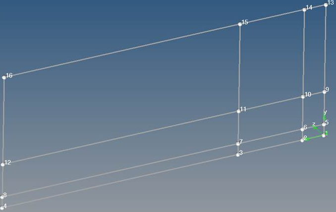
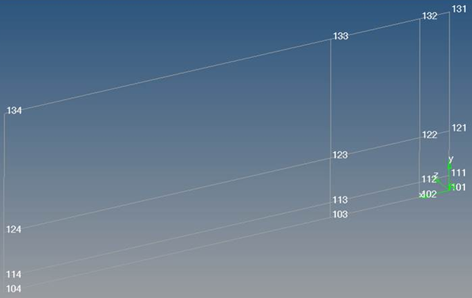
Rectangular grid Using this method, you can renumber a rectangular regular array of elements or quads in two perpendicular directions in a user-defined coordinate system (Cartesian or cylindrical).
The steps are the same as the spatial method, but in this case a local coordinate system must be used to match the primary numbering directions and the mesh is expected to be a rectangular pattern of quads. You must define 3 different increments.Figure 2. Before Element Renumber 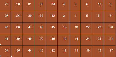
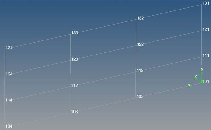
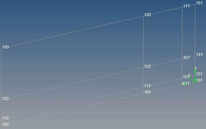
Figure 3. After Element Renumber: X increment by 1, Y increment by 100 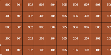
Adjacent Using the adjacent method, renumbering is based on element/node connectivity directions instead of system directions. This method works only with quadrilateral elements (without any triangular elements) and should have a mapped (regular) pattern.
- Enter the Start ID.
- Click Options on the guide bar.
- Select a starting node or element.
- Select an element/node for the primary, secondary, and
tertiary directions and define their ID increments.
These should be connected to the starting element.
- Click
-
On the guide bar, click one of the following:
 - Apply and stay in the tool
 - Apply and close the tool
 - Exit the tool without applying
How the Tolerance Setting Affects the Renumber Result
The tolerance is used to group the nodes/elements in the correct order for renumbering.