Systems
Local coordinate systems can be used for setting up loads/boundary conditions that do not act in the global axis direction, transforming results, defining material orientation, and many other operations.
Create Systems
-
From the Model ribbon, click the Systems
tool.
Figure 1. 
-
Select the Node or Location defining the origin of the system.
The system manipulator is placed at the selected node or location and the Axis-Plane button is activated.Note: By default, the system manipulator is oriented based on the location of the origin. If the selected node belongs to a shell element, the manipulator by default uses the shell normals to orient itself.
- Optional: Use the microdialog options to change the system type and axis-plane combinations.
-
Drag the Axis and Plane handles in the graphics to manipulate the system to the
desired orientation.
Tip:
- Hold Ctrl and select the desired locations or nodes in the graphics to quickly define the Axis and Plane definitions for the system.
- You can edit the systems visualization style using the controls in
the guide bar menu
 .
.
-
On the guide bar, complete one of the following:
- Click
 to apply and stay in the tool.
 - Click
 to apply and close the tool.
 - Click
 to exit the tool without applying.
- Click
System Microdialog Options

- Choose between a rectangular, cylindrical, or spherical system.
- Specify the Axis and Plane combinations for the system being created
(X-XY, Y-YZ, Z-ZX). The system can either be node-based (associative) or
coordinate-based (non-associative).Note: The exact conventions shown in the drop-down will vary based on the current solver interface.

- Toggle between reduced (default) and full manipulator modes.
- The full manipulator mode displays all 3 axis handles simultaneously.
Selecting any of the axis handles further displays the corresponding
plane handles for the selected axis.
Figure 2. 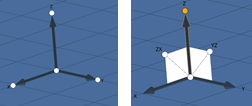
Note: Irrespective of the handle used, the system entity created will always respect the Axis-Plane combo that the solver allows. 
- Align the system manipulator to the global coordinate system.

- Assign an input reference system with respect to which the system will
be defined.Note: Once the input reference system is assigned, the system button is shown with a tick mark
 indicating that an input reference
system is assigned. The assignment is remembered until you exit the
tool.
indicating that an input reference
system is assigned. The assignment is remembered until you exit the
tool.
Manipulator Microdialog Options
 ,
,  ,
, 
- Align the selected system handle to one of the global axes or manually type the vector components.

- Reverse the direction of the system handle.

- Translate or rotate the system with precision.

- Align the system handle normal or parallel to the current view.

- Edit System handle (Origin/Axis/Plane) coordinates.

- Reset the position of the handles to move closer to the manipulator.

- Opens a node selector, which allows you to select the node graphically
or, alternatively, use advanced selection to manually input the node
ID.Note: The grayed-out field next to the node button displays the id of the node that the system handle is snapped to. The node button is shown with a tick mark indicating that the handle is snapped
to a model node. If the handle is not snapped to any model node, the
field indicates the same with a “0”, and the manipulator creates a
temp node at the location, thereby allowing the system to remain
valid.
Edit Systems
-
To open the System tool in edit mode, do one of the following from idle:
- Double-click on a System
- Right-click on a System and select Edit from the context menu.
- Select a System, then access the tool from the ribbon icon.
- Utilize any of the actions noted above to modify the System type or orientation.
-
On the guide bar, click
 to confirm the change and
  to exit the tool.
Tip:
- While in edit mode, you can change the system type using the type and axis-plane drop-downs, and the context automatically handles the conversion of the coordinate system.
- If your model does not contain nodes, use the location selector to pick an origin and modify the (Origin/Plane/Axis) handle coordinates using the microdialog/snaps.
- Refer to the entity status icon on the guide bar for status and feedback. Clicking the icon will fit the view to the current system.
- Changes made in the System tool are automatically committed to the database. If a change is made that invalidates the System (for example, clearing the Origin node), the system will turn gray, and the database will not be updated until the system is made valid again. The entity status icon and error flags on the selectors help identify required inputs.
System Assignment
Systems are available for assignment to properly control the orientation of entities like loads, transformations of parts, model has degrees of freedom for movement during simulation among many other applications.
-
From the Model ribbon, click the Assign Systems
satellite tool.
Figure 3. 
- Optional:
On the guide bar, click to access system visualization options.
-
Assign or unassign systems.
Option Description Assign - Select a system to assign using the first selector.
- Using the second selector, select the nodes, loads, or systems to be assigned the system.
- Complete one of the following:
- Click
 to apply and stay in the
tool.
to apply and stay in the
tool. - Click
 to apply and close the
tool.
to apply and close the
tool. - Click
 to exit the tool without
applying.
to exit the tool without
applying.
Both selectors need to be populated to for the assign action buttons to be active.
- Click
Unassign - Using the second selector, select components or properties that have a material assigned to them.
- Complete one of the following:
- Click
 to unassign the system and
remain in the tool.
to unassign the system and
remain in the tool. - Click
 to unassign the system and
exit the tool.
to unassign the system and
exit the tool. - Click
 to exit the tool without
unassigning.
to exit the tool without
unassigning.
Only the second selector can be populated to perform an unassignment.
- Click
Note: Set Reference and/or Set Displacement are a required input for node-based
assignment.