Create Vectors
Define vectors in 3D space.
In the modeling window, vectors are displayed as an arrow with the letters VEC and their vector size value at the tail end. By default, vectors are displayed using a representation of 100% of their actual length.
You can create several vectors at a time by selecting nodes and either a magnitude, or by deriving them from a line tangent or surface normal. Single vectors can be created by selecting two nodes or by deriving them from the cross product of two existing vectors.
-
From the Model ribbon, click the
Vectors tool.
Figure 1. 
-
Choose a creation method from the drop-down on the guide bar.
Option Description Base and magnitude - Select one or more nodes, FE edges, or faces at which to place vectors.
- Define a magnitude.
- Optionally, click
 to assign the vector to a local
coordinate system.
to assign the vector to a local
coordinate system.For example, if you define a vector in the global z-direction, then assign a system, the result will be a vector pointing in the z-direction of the local system.
- Click
 to adjust direction components with
the Vector tool.
to adjust direction components with
the Vector tool.
Figure 2. 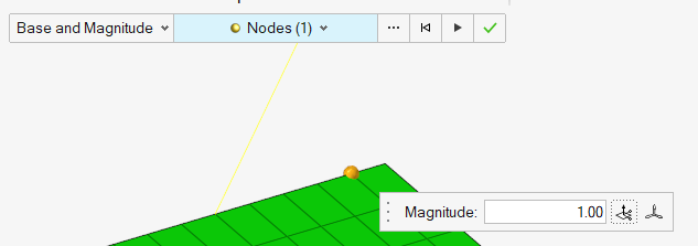
Two nodes Select two nodes or locations to create a vector from node one to node two. Figure 3. 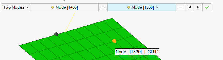
Cross Product - Select a node or location at which to place the new vector.
- Select two existing vectors to derive a perpendicular vector.
- Enter a magnitude or inherit the magnitude of one of the two selected vectors.
Figure 4. 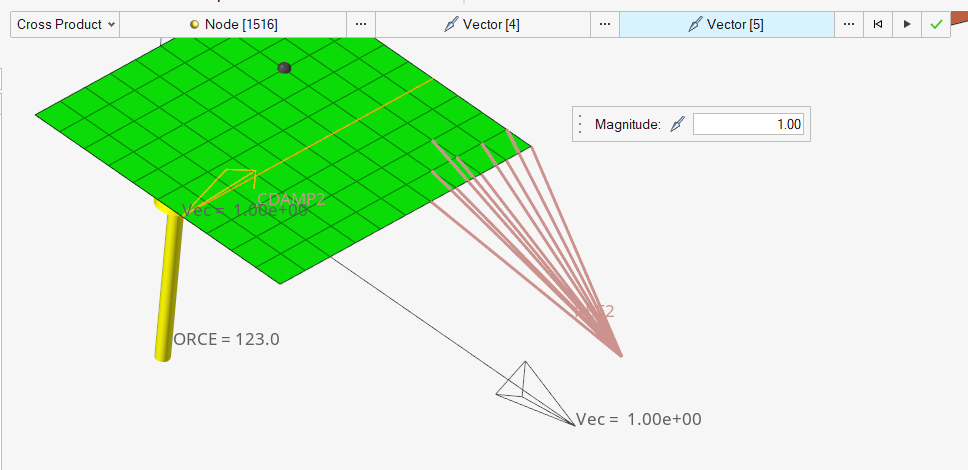
Line Tangent - Select a node, face, or edge at which to place a vector.
- Select lines to create tangent vector projections.
The resulting vector(s) will be created on all nodes selected.
- Enter the magnitude or calculate it automatically using parameterization. For a curve tangent, this is the value of the parametric curve derivative.
Figure 5. 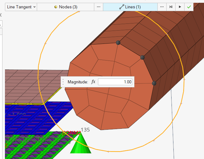
Surface Normal - Select a node, face, or edge at which to place a vector.
- Select surfaces to create normal vector projections
The resulting vector(s) will be created on all nodes selected.
- Enter the magnitude or calculate it automatically using parameterization. For a surface normal the value is defined by the length of the cross product of the surface parametric derivatives.
Figure 6. 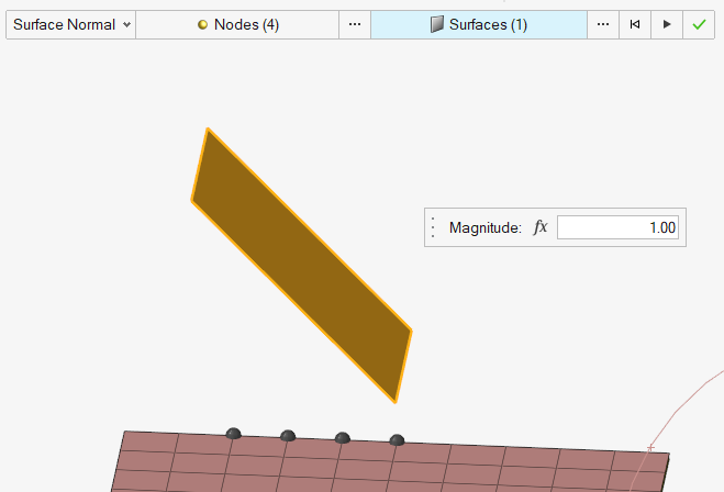
-
On the guide bar, click one of the following:
 - Apply and stay in the tool
 - Apply and close the tool