Create Representations
Part representations can be automatically created using BatchMesher, powered by the representation control.
- In the Part Browser, right-click on part assemblies or parts and select from the context menu.
-
In the Change Representation dialog, Create tab, select a
single or multiple representations to be created for the selected part(s).
This dialog also displays if the representations already exist. The count is shown in the Available column.The availability of the selected representation in the repository is displayed next to the representation type within parentheses.
Figure 1. Change Representation Dialog 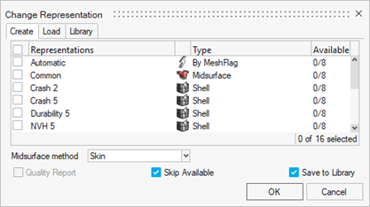
- Optional:
To specify automatic selection of which representations should be created,
select the Automatic check box.
Selected parts are checked to see if the PDM meshflag metadata is defined. These mesh flags are paired with the corresponding mesh flags on the control. When matching pairs are found, the given controls is used to create a representation for that part.
- Optional: To save the newly created representations to the Part Library, select the Save to Library check box.
- Optional:
If the Common representation is to be created, select a method to be used for
extracting the midsurface from the CAD representation.
The default method is Skin.
- Optional: For Shell representations, select the Quality Report check box to request a quality report for the resultant mesh.
-
Click OK.
All representations are sent to the BatchMesher for processing in parallel. Upon completion, all representations are automatically saved to the repository.
Each representation is created by taking its input representation as the source model. CAD and Common can be used as input representations. Common is the input for Shell type representations and CAD is the input for all other types. You can review the input representation required for each control in the Representation Control Manager. If the input representations are available, they do not need to be loaded into the session since they are sent directly to the BatchMesher for processing. When creating a Shell representation, in case the Common representation does not exist, it is automatically generated by extracting the midsurface from the CAD representation and then used as input to the Shell representation.
Properties and materials are generated from the PDM Metadata, if available, during representation creation. The PDM PID is assigned to the component and property IDs, the PDM MID and PDM Material are assigned to the material, and the PDM Thickness is assigned to the thickness attribute of the property. If the PDM Thickness is blank, the CAD thickness calculated during the midsurface operation is automatically assigned to the thickness attribute of the property.
Note: You can select the number of BatchMesher jobs running in parallel from the Assembly tab of . The default setting is Auto, which utilizes all available CPUs except for one.Figure 2. Preferences Dialog 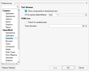
-
In the BatchMesh dialog, specify how representations are
imported.
- Click Yes to import all representations into the session.
- Click No to not import the representations into
the session. Note: The representations will be available in the Load Representation dialog.