Power-off in a Straight Line
A Power-off in a straight line event simulates the dynamics of a vehicle due to a sudden removal of drive torque.
The Altair Driver maintains the straight line path and controls the throttle. Engine motoring torque is not applied after the throttle torque is removed.
The Power off in straight line event is supported by the Cars & Small Trucks, Heavy Trucks, and Two-Wheeler vehicle libraries. Automated output reports are available to plot the results.
Parameters
| Parameter Name | Description |
|---|---|
| Units | Describes the Length, Velocity, and Acceleration units.
|
| Velocity | The initial speed of the vehicle during the steady state driven portion of the event. |
| Throttle step begin | The absolute time, in seconds, when the throttle torque begins to be removed. |
| Throttle delay | The time interval from issuing the throttle removal command until the actual throttle torque starts to decrease. |
| Throttle step duration | The length of the time the throttle controller takes to remove all torque from the drivetrain using a step function. |
| End time | Absolute end time of the event, in seconds. |
- Initial Static and Steering Ratio
-
Run initial static Enables the execution of the initial static simulation. Compute steering ratio Enables the automatic calculation of the steering ratio at the beginning of the event simulation. Turn this option off to use a different Steering ratio (default value of 16 is provided). - End Time Calculation
- The parameters defined above are also used to determine the total simulation time.
The simulation time is specified in the Altair Drive File (.adf),
as shown below:
Figure 1. Maneuvers List Block for a Power-off in a Straight Line Event 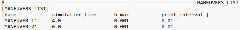
For more information see the Altair Driver File Blocks topic.
In a Power-off in a Straight Line event:- MANEUVER_1 represents the initial steady state driven portion of the event.
- MANEUVER_2 corresponds to the portion of the event where the throttle torque is removed, while maintaining a straight-line path.
The total simulation time for each maneuver is calculated using the following equation:Maneuver Simulation Time Equation Maneuver 1 Throttle step beginManeuver 2 End time-Throttle step beginThe total simulation time corresponds to the sum of the total simulation times for Maneuver 1 and Maneuver 2.
Controller Settings
- Non-leaning events (Cars/Trucks)
- LONGITUDINAL – TRACTION CONTROLLER SETTINGS
- Use additional control: Enables the additional feedback control for the traction
control. The gains for the controller can be edited by toggling this check
box.
Kp Proportional gain for the feedback PID controller Ki Integral gain for the feedback PID controller Kd Derivative gain for the feedback PID controller
- Use additional control: Enables the additional feedback control for the traction
control. The gains for the controller can be edited by toggling this check
box.
- Leaning events (Two-wheelers)
- LONGITUDINAL – TRACTION CONTROLLER SETTINGS
- Use additional control: Enables the additional feedback control for the traction
control. The gains for the controller can be edited by toggling this check
box.
Kp Proportional gain for the feedback PID controller Ki Integral gain for the feedback PID controller Kd Derivative gain for the feedback PID controller
- Use additional control: Enables the additional feedback control for the traction
control. The gains for the controller can be edited by toggling this check
box.
Signal Settings
Use the signal settings to set minimum, maximum, smooth frequency and initial values for Steering, Throttle, Brake, Gear, and Clutch signals output by the driver.
The smoothing frequency is used to control how fast the Driver changes signals. Only closed loop control signals from the Driver are smoothed. Open loop signals are not smoothed.
Road Settings
- Flat Event
- Uses a flat smooth road for the event with no required road file.When the Flat Event is selected, the Graphics Setting option is available with the following parameters:
- View path centerline: Enables the visualization of the event path.
- This check box is disabled for open loop events without a path.
- View grid graphics: Enables the visualization of the road grid graphics.
- When view grid graphics check box is toggled, road grid parameters can be edited in the Grid Settings tab.
Grid length Defines the length of the road. Enter a positive value in the model units. Grid Width Defines the width of the road. Enter a positive value in the model units. Grid X offset Gives a distance offset to the road graphics in the longitudinal direction. Enter a positive value in the model units. Grid Y offset Gives a distance offset to the road graphics in the lateral direction. Enter a positive value in the model units.
- View path centerline: Enables the visualization of the event path.
- Road File
- The road file option enables the selection of a road file to be used in the event. Using this option, all tires in the model consider the event specified road file instead of the file included in the tire entities.
- Tires
- Using Tire as road selection option, the road file specified in the tire entity is used in the events simulation.
Simulation Settings
- Analysis Parameters
- Define the numerical and output settings for the simulation:
Parameter Name Description Print interval The time step between successive outputs of simulation results. Real-Time Empowered When enabled, MotionSolve builds the FMU of the vehicle and solves it in real-time. Code generation When enabled, the C code for the MotionSolve Vehicle model excluding the driver and tire will be generated. This code can be used to compile and build an FMU, which can be used with any FMU compatible software. For more information see the Parameters: Simulation - Attributes topic.
- Dynamic Settings
- Defines the simulation control parameters for a time-domain-based nonlinear dynamic analysis. For more information see the Parameters: Transient Solver - Attributes topic.
- Static Settings
- Defines the solution control parameters for static and quasi-static analysis. For more information see the Parameters: Static Solver - Attributes topic.
Automated Output Report
| Report Name | Report Signals |
|---|---|
| Engine Torque and Throttle |
|
| Steering Wheel Angle, Vehicle CG Displacement and Velocity |
|
| Vehicle Slip Angles |
|
| Steer/Suspension Travel |
|
| Vertical Tire Forces |
|
| Lateral Tire Forces |
|
| Tire Lateral Slip |
|
| Longitudinal Tire Forces |
|
| Tire Longitudinal Slip |
|
| Vertical Tire Forces |
|
| Axle Loads |
|
| Pitch, Front Dive and Rear Lift vs. Longitudinal Acceleration |
|