J-turn Steering
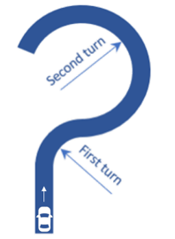
The J-turn event (or Fishhook maneuver) simulates a vehicle's dynamic response to a sudden, sharp steering input in one direction, followed by a brief pause (dwell time) to let the vehicle to react, and then an equally sharp steering input in the opposite direction.
The event is used to characterize the stability of vehicles. Both steer directions can be run by reversing the sign of the steering inputs. The Altair Driver is used to maintain a constant speed.
The J-turn event is supported by the Cars & Small Trucks, Heavy Trucks, and Two-Wheeler vehicle libraries. Automated output reports are available to plot the results.
The J-Turn event follows the ISO +7401-2003 - Road Vehicles-Lateral transient response test methods-Open-loop test methods. It is also designed to simulate the NHTSA fishhook test as described in DOT publication DOT HS 809 705, “Phase VIII of NHTSA’s Light Vehicle Rollover Research Program-A Demonstration of the Dynamic Tests Developed for NHTSA’s NCAP Rollover Rating System”.
Parameters
| Parameter Name | Description |
|---|---|
| Units | Describes the Length, Velocity, and Acceleration units.
|
| Velocity | Initial vehicle velocity. |
| Initial power run | The time period at the start of the event used to ensure the vehicle reached the steady-state condition before the steering input begins. |
| First turn direction | Defines the steer direction used in the first turn. |
| First steer angle* | Angle in degrees of the initial steer input. A positive number turns the vehicle right and a negative number turns the vehicle left (as seen by the driver). |
| First lean angle** | The demand lean angle for the initial turn in degrees. |
| First step duration | Time required to apply the First steer angle to the steering wheel (the angle is applied using a step function). |
| First turn duration | Time duration for which the steering input remains fixed at the specified First steer angle. |
| Second turn direction | Defines the direction used in the second turn. |
| Second steer angle* | Steering angle in degrees of the second steer input. |
| Second lean angle** | The demand lean angle for the second turn in degrees. |
| Second step duration | The time required to apply the Second steer angle to the steering wheel (the angle is applied using a step function). |
| Second turn duration | Time duration for which steering input remains fixed at the specified Second steer angle. |
*Applicable only for Cars/Trucks (that is, Non-leaning events).
**Applicable only for Two-wheeler (that is, Leaning events).
- Initial Static and Steering Ratio
-
Run initial static Enables the execution of the initial static simulation. Compute steering ratio Enables the automatic calculation of the steering ratio at the beginning of the event simulation. Turn this option off to use a different Steering ratio (default value of 16 is provided). - End Time Calculation
- The parameters defined above are also used to determine the total simulation time.
The simulation time is specified in the Altair Drive File (.adf),
as shown below:
Figure 2. Maneuvers List Block for a J-Turn Steering Event 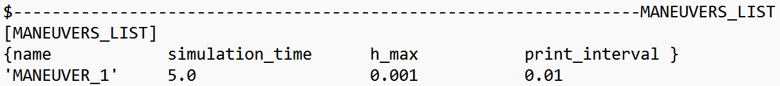
For more information see the Altair Driver File Blocks topic.
The simulation time is calculated using the following equation:Maneuver Simulation Time Equation Maneuver 1 Initial power run+First step duration+First turn duration+Second step duration+Second turn duration
Controller Settings
- Non-leaning events (Cars/Trucks)
- LONGITUDINAL – TRACTION CONTROLLER SETTINGS
- Use additional control: Enables the additional feedback control for the traction
control. The gains for the controller can be edited by toggling this check
box.
Kp Proportional gain for the feedback PID controller Ki Integral gain for the feedback PID controller Kd Derivative gain for the feedback PID controller
- Use additional control: Enables the additional feedback control for the traction
control. The gains for the controller can be edited by toggling this check
box.
- Leaning events (Two-wheelers)
- LONGITUDINAL – TRACTION CONTROLLER SETTINGS
- Use additional control: Enables the additional feedback control for the traction
control. The gains for the controller can be edited by toggling this check
box.
Kp Proportional gain for the feedback PID controller Ki Integral gain for the feedback PID controller Kd Derivative gain for the feedback PID controller
- Use additional control: Enables the additional feedback control for the traction
control. The gains for the controller can be edited by toggling this check
box.
Signal Settings
Use the signal settings to set minimum, maximum, smooth frequency and initial values for Steering, Throttle, Brake, Gear, and Clutch signals output by the driver.
The smoothing frequency is used to control how fast the Driver changes signals. Only closed loop control signals from the Driver are smoothed. Open loop signals are not smoothed.
Road Settings
- Flat Event
- Uses a flat smooth road for the event with no required road file.When the Flat Event is selected, the Graphics Setting option is available with the following parameters:
- View path centerline: Enables the visualization of the event path.
- This check box is disabled for open loop events without a path.
- View grid graphics: Enables the visualization of the road grid graphics.
- When view grid graphics check box is toggled, road grid parameters can be edited in the Grid Settings tab.
Grid length Defines the length of the road. Enter a positive value in the model units. Grid Width Defines the width of the road. Enter a positive value in the model units. Grid X offset Gives a distance offset to the road graphics in the longitudinal direction. Enter a positive value in the model units. Grid Y offset Gives a distance offset to the road graphics in the lateral direction. Enter a positive value in the model units.
- View path centerline: Enables the visualization of the event path.
- Road File
- The road file option enables the selection of a road file to be used in the event. Using this option, all tires in the model consider the event specified road file instead of the file included in the tire entities.
- Tires
- Using Tire as road selection option, the road file specified in the tire entity is used in the events simulation.
Simulation Settings
- Analysis Parameters
- Define the numerical and output settings for the simulation:
Parameter Name Description Print interval The time step between successive outputs of simulation results. Real-Time Empowered When enabled, MotionSolve builds the FMU of the vehicle and solves it in real-time. Code generation When enabled, the C code for the MotionSolve Vehicle model excluding the driver and tire will be generated. This code can be used to compile and build an FMU, which can be used with any FMU compatible software. For more information see the Parameters: Simulation - Attributes topic.
- Dynamic Settings
- Defines the simulation control parameters for a time-domain-based nonlinear dynamic analysis. For more information see the Parameters: Transient Solver - Attributes topic.
- Static Settings
- Defines the solution control parameters for static and quasi-static analysis. For more information see the Parameters: Static Solver - Attributes topic.
Automated Output Report
| Report Name | Report Signals |
|---|---|
| Steering Wheel Angle, Lateral Acceleration, Vehicle Velocity and Yaw Rate |
|
| Vehicle CG Displacement |
|
| Roll Angle and Side Slip Angles |
|
| Vertical Tire Forces |
|
| Lateral Tire Forces |
|
| Tire Lateral Slip |
|
| Longitudinal Tire Forces |
|
| Tire Longitudinal Slip |
|