Stability Analysis
The Stability Analysis event can be used to simulate two-wheeler models on various road surfaces to evaluate the weave and wobble modes of the vehicle. A user-defined road property file determines the road input.
The Stability Analysis event is supported by the Two-Wheeler vehicle libraries.
 |
 |
|
|
|
Parameters
| Parameter Name | Description |
|---|---|
| Units | Describes the Length, Velocity, and Acceleration units.
|
| Velocity | Constant demand velocity input. |
| Steer release time | Used in the Pulse force and General force analysis mode. Time at which steer control is released. Note: For the Linear analysis mode, the steer control is released at the end time and a Linear analysis is run. |
| Disturbance start time | Used in the Pulse force analysis mode. Start time for the pulse force disturbance defined in the Force inputs tab. |
| End time | End time for the simulation. |
| Path profile | Defines the path the vehicle follows. Three options are available:
|
| Analysis mode | Defines the type of analysis in the event. Three options are available:
|
- Initial Static and Steering Ratio
-
Run initial static Enables the execution of the initial static simulation. Compute steering ratio Enables the automatic calculation of the steering ratio at the beginning of the event simulation. Turn this option off to use a different Steering ratio (default value of 16 is provided). - End Time Calculation
- The parameters defined above are also used to determine the total simulation time.
The simulation time for each maneuver is specified in the Altair Drive File
(.adf) and differs between Linear Analysis and Pulse
Force/General Force:
- Linear Analysis
-
Figure 2. Maneuvers List Block for a Stability Analysis Event of Type Linear 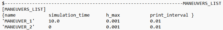
In a Stability Analysis event:- MANEUVER_1 represents the initial part of the event where vehicle control is active.
- MANEUVER_2 corresponds to the part of the event after steer control is released.
For more information see the Altair Driver File Blocks topic.
In the Linear Analysis type, since steering control is deactivated at the end of the simulation, the simulation time for MANEUVER_2 is set to 0.
- Pulse Force/General Force
-
Figure 3. Maneuvers List Block for a Stability Analysis Event of Type Pulse Force/General Force 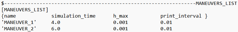
The simulation times are calculated using the following equations:Maneuver Simulation Time Equation Maneuver 1 Steer release timeManeuver 2 End Time - Steer release time
The total simulation time corresponds to the sum of the total simulation times for Maneuver 1 and Maneuver 2.
Controller Settings
- Use additional control: Enables the additional feedback control for the traction
control. The gains for the controller can be edited by toggling this check box.
Kp Proportional gain for the feedback PID controller Ki Integral gain for the feedback PID controller Kd Derivative gain for the feedback PID controller
- The Lean PID and Lateral Error PID controllers only apply to leaning vehicles (for
example, motorcycles and scooters).Steer control: Control mode for steering can be switched between ‘MOTION’ and ‘TORQUE’. When set to ‘MOTION’, the steering input is defined by the steering wheel angle. When set to ‘TORQUE’, the steering is controlled via the applied torque on the steering wheel.
- Lean control
- The Lean PID takes as input a demand lean angle and outputs front fork
(steering) angle. For open loop events the lean angle demand is a function of
time. For closed loop path following events the demand lean angle is computed
based on the vehicle speed and the path curvature with a correction for lateral
path error.
Kp Proportional gain for the lean controller Ki Integral gain for the lean controller Kd Derivative gain for the lean controller - Lateral error control
- The Lateral Error PID takes as input the predicted lateral path error and outputs an increment to the demanded lean angle. The lateral error is computed by predicting the vehicle’s lateral position relative to the path by the look ahead time in the future. The Lateral Error PID acts to lean the vehicle toward the path.
For more information see the Leaning Two and Three Wheeler Vehicles and Gain Tuning for Leaning Two and Three Wheeler Vehicles topics.
Signal Settings
Use the signal settings to set minimum, maximum, smooth frequency and initial values for Steering, Throttle, Brake, Gear, and Clutch signals output by the driver.
The smoothing frequency is used to control how fast the Driver changes signals. Only closed loop control signals from the Driver are smoothed. Open loop signals are not smoothed.
Road Settings
- Flat Event
- Uses a flat smooth road for the event with no required road file.When the Flat Event is selected, the Graphics Setting option is available with the following parameters:
- View path centerline: Enables the visualization of the event path.
- This check box is disabled for open loop events without a path.
- View grid graphics: Enables the visualization of the road grid graphics.
- When view grid graphics check box is toggled, road grid parameters can be edited in the Grid Settings tab.
Grid length Defines the length of the road. Enter a positive value in the model units. Grid Width Defines the width of the road. Enter a positive value in the model units. Grid X offset Gives a distance offset to the road graphics in the longitudinal direction. Enter a positive value in the model units. Grid Y offset Gives a distance offset to the road graphics in the lateral direction. Enter a positive value in the model units.
- View path centerline: Enables the visualization of the event path.
- Road File
- The road file option enables the selection of a road file to be used in the event. The road property file used in this option overrides the road property files used in the Tire entities within the model. The road property file should be compatible with the tire property file that is used in the vehicle.
- Tires
- Using Tire as road selection option, the road file specified in the tire entity is used in the events simulation.
Simulation Settings
- Analysis Parameters
- Define the numerical and output settings for the simulation:
Parameter Name Description Print interval The time step between successive outputs of simulation results. For more information see the Parameters: Simulation - Attributes topic.
- Dynamic Settings
- Defines the simulation control parameters for a time-domain-based nonlinear dynamic analysis. For more information see the Parameters: Transient Solver - Attributes topic.
- Static Settings
- Defines the solution control parameters for static and quasi-static analysis. For more information see the Parameters: Static Solver - Attributes topic.
- Linear Settings
- Defines the solution control parameters for a linear analysis. For more information see the Parameters: Linear Solver - Attributes.
Automated Output Report
| Report Name | Report Signals |
|---|---|
| Analysis Type = Linear |
|
| Analysis Type = Pulse Force/General Force |
|