Single Lane Change
A Single lane change event drives the vehicle through a single lane change, attempting to follow the centerline of the defined lane.
You can define the speed of the lane change, along with the lane dimensions. A steering controller is used to follow the path and a torque controller is used to maintain speed through the event. The event supports right and left lane changes.
The Single Lane change event is supported by the Cars & Small Trucks, Heavy Trucks, and Two-Wheeler vehicle libraries. Automated output reports are available to plot the results.
Parameters
| Parameter Name | Description |
|---|---|
| Units | Describes the Length, Velocity, and Acceleration units.
|
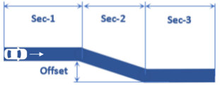
| Lateral offset | Offset distance of the lane. |
| Length- Section 1 | Length of the initial straight section of road. |
| Length- Section 2 | Longitudinal length of the initial lane change section of road. |
| Length- Section 3 | Length of the recovery straight section of road. |
| Velocity | The initial speed of the vehicle. |
| Turn direction | Direction the vehicle turns during the event (as seen by the driver). |
- Initial Static and Steering Ratio
-
Run initial static Enables the execution of the initial static simulation. Compute steering ratio Enables the automatic calculation of the steering ratio at the beginning of the event simulation. Turn this option off to use a different Steering ratio (default value of 16 is provided). - End Time Calculation
- The parameters defined above are also used to determine the total simulation time.
The simulation time is specified in the Altair Drive File (.adf),
as shown below:
Figure 2. Maneuvers List Block for a Single Lane Change Event 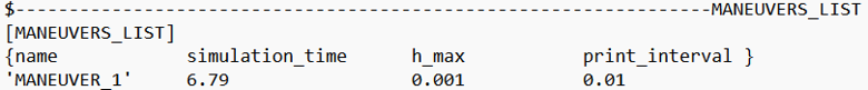
For more information see the Altair Driver File Blocks topic.
The simulation time is calculated using the following equation:Maneuver Simulation Time Equation Maneuver 1 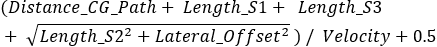
Where Distance_CG_Path is the distance between the initial position of the vehicle body’s CG, and the origin of the path reference marker, as defined in the Altair Driver property sheet.
Controller Settings
- Non-leaning events (Cars/Trucks)
- LONGITUDINAL – TRACTION CONTROLLER SETTINGS
- Use additional control: Enables the additional feedback control for the traction
control. The gains for the controller can be edited by toggling this check
box.
Kp Proportional gain for the feedback PID controller Ki Integral gain for the feedback PID controller Kd Derivative gain for the feedback PID controller
- Use additional control: Enables the additional feedback control for the traction
control. The gains for the controller can be edited by toggling this check
box.
- Leaning events (Two-wheelers)
- LONGITUDINAL – TRACTION CONTROLLER SETTINGS
- Use additional control: Enables the additional feedback control for the traction
control. The gains for the controller can be edited by toggling this check
box.
Kp Proportional gain for the feedback PID controller Ki Integral gain for the feedback PID controller Kd Derivative gain for the feedback PID controller
- Use additional control: Enables the additional feedback control for the traction
control. The gains for the controller can be edited by toggling this check
box.
Road Settings
- Flat Event
- Uses a flat smooth road for the event with no required road file.When the Flat Event is selected, the Graphics Setting option is available with the following parameters:
- View path centerline: Enables the visualization of the event path.
- This check box is disabled for open loop events without a path.
- View grid graphics: Enables the visualization of the road grid graphics.
- When view grid graphics check box is toggled, road grid parameters can be edited in the Grid Settings tab.
Grid length Defines the length of the road. Enter a positive value in the model units. Grid Width Defines the width of the road. Enter a positive value in the model units. Grid X offset Gives a distance offset to the road graphics in the longitudinal direction. Enter a positive value in the model units. Grid Y offset Gives a distance offset to the road graphics in the lateral direction. Enter a positive value in the model units.
- View path centerline: Enables the visualization of the event path.
- Road File
- The road file option enables the selection of a road file to be used in the event. The road property file used in this option overrides the road property files used in the Tire entities within the model. The road property file should be compatible with the tire property file that is used in the vehicle.
- Tires
- Using Tire as road selection option, the road file specified in the tire entity is used in the events simulation.
Simulation Settings
- Analysis Parameters
- Define the numerical and output settings for the simulation:
Parameter Name Description Print interval The time step between successive outputs of simulation results. Real-Time Empowered When enabled, MotionSolve builds the FMU of the vehicle and solves it in real-time. Code generation When enabled, the C code for the MotionSolve Vehicle model excluding the driver and tire will be generated. This code can be used to compile and build an FMU, which can be used with any FMU compatible software. For more information see the Parameters: Simulation - Attributes topic.
- Dynamic Settings
- Defines the simulation control parameters for a time-domain-based nonlinear dynamic analysis. For more information see the Parameters: Transient Solver - Attributes topic.
- Static Settings
- Defines the solution control parameters for static and quasi-static analysis. For more information see the Parameters: Static Solver - Attributes topic.
Automated Output Report
| Report Name | Report Signals |
|---|---|
| Steering Input, Vehicle Acceleration and Engine Torque |
|
| Vehicle Velocities |
|
| Vehicle Slip Angles |
|
| Roll Angle |
|
| Steer/Suspension Travel |
|
| Driver Steering Control Signals |
|
| Vehicle Sideslip vs. Acceleration |
|
| Steering Wheel Angle vs. Vehicle Sideslip Angle |
|
| Vehicle CG Displacement |
|
| Vertical Tire Forces |
|
| Lateral Tire Forces |
|
| Tire Lateral Slip |
|
| Longitudinal Tire Forces |
|
| Tire Longitudinal Slip |
|