Constant Radius
A Constant radius event simulates a vehicle driving in a circular path, typically with increasing speed. The event predicts the vehicles roll and understeer characteristics with increasing lateral acceleration.
The event maintains a constant turn radius and varies the vehicle velocity to produce increasing amounts of lateral acceleration. Steering and torque controllers maintain the path and the speed of the vehicle through the event.
The constant radius event is supported by the Cars & Small Trucks, Heavy Trucks, and Two-Wheeler vehicle libraries. Automated output reports are available to plot the results.
Parameters
| Parameter Name | Description |
|---|---|
| Units | Describes the Length, Velocity, and Acceleration units.
|
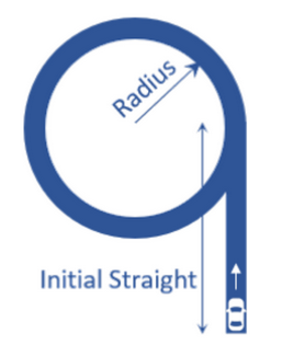
| Radius | Radius of the circle that the vehicle CG follows during the constant radius portion of the event. |
| Initial straight | Straight distance section of the event before the constant radius portion. |
| Initial velocity | Initial vehicle velocity. |
| Final velocity | Final vehicle velocity desired in the simulation. |
| Initial lateral acceleration | Estimated initial lateral acceleration. This value is not editable and is calculated using the initial speed and the radius parameters. |
| Final lateral acceleration | Estimated final lateral acceleration. This value is not editable and is calculated using the initial speed and the radius parameters. |
| Turn direction | Direction the vehicle turns during the event (as seen by the driver). |
| Transient time | Time duration for which vehicle accelerates/decelerates after achieving steady state. |
- Initial Static and Steering Ratio
-
Run initial static Enables the execution of the initial static simulation. Compute steering ratio Enables the automatic calculation of the steering ratio at the beginning of the event simulation. Turn this option off to use a different Steering ratio (default value of 16 is provided). - End Time Calculation
- The parameters defined above are also used to determine the total simulation time.
The maximum simulation time for each maneuver is specified in the Altair Drive File
(.adf), as shown below:
Figure 2. Maneuvers List Block for a Constant Radius Event 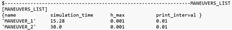
In a Constant Radius event:- MANEUVER_1 represents the initial straight-line section.
- MANEUVER_2 corresponds to the constant-radius portion of the event.
The maximum simulation time for each maneuver is calculated using the following equations:Maneuver Simulation Time Equation Maneuver 1 (Initial straight+2*Radius*Entry Angle)/Initial Velocity+5Maneuver 2 Transient timeThe actual simulation time is defined by the end conditions specified in each maneuver:Figure 3. Maneuver Blocks for a Constant Radius Event 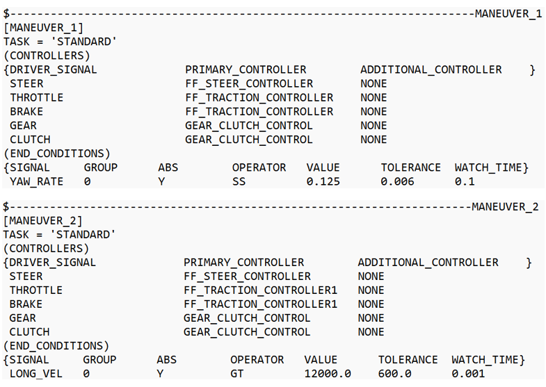
- MANEUVER_1 terminates when
 is true for 0.1 seconds continuously.
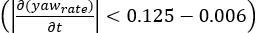
 - MANEUVER_2 terminates when
 is true for 0.001 seconds continuously.
For more information see the Altair Driver File Blocks topic.
The total simulation time corresponds to the sum of the actual simulation times for Maneuver 1 and Maneuver 2.
Controller Settings
- Non-leaning events (Cars/Trucks)
- LONGITUDINAL – TRACTION CONTROLLER SETTINGS
- Use additional control: Enables the additional feedback control for the traction
control. The gains for the controller can be edited by toggling this check
box.
Kp Proportional gain for the feedback PID controller Ki Integral gain for the feedback PID controller Kd Derivative gain for the feedback PID controller
- Use additional control: Enables the additional feedback control for the traction
control. The gains for the controller can be edited by toggling this check
box.
- Leaning events (Two-wheelers)
- LONGITUDINAL – TRACTION CONTROLLER SETTINGS
- Use additional control: Enables the additional feedback control for the traction
control. The gains for the controller can be edited by toggling this check
box.
Kp Proportional gain for the feedback PID controller Ki Integral gain for the feedback PID controller Kd Derivative gain for the feedback PID controller
- Use additional control: Enables the additional feedback control for the traction
control. The gains for the controller can be edited by toggling this check
box.
Signal Settings
Use the signal settings to set minimum, maximum, smooth frequency and initial values for Steering, Throttle, Brake, Gear, and Clutch signals output by the driver.
The smoothing frequency is used to control how fast the Driver changes signals. Only closed loop control signals from the Driver are smoothed. Open loop signals are not smoothed.
Road Settings
- Flat Event
- Uses a flat smooth road for the event with no required road file.When the Flat Event is selected, the Graphics Setting option is available with the following parameters:
- View path centerline: Enables the visualization of the event path.
- This check box is disabled for open loop events without a path.
- View grid graphics: Enables the visualization of the road grid graphics.
- When view grid graphics check box is toggled, road grid parameters can be edited in the Grid Settings tab.
Grid length Defines the length of the road. Enter a positive value in the model units. Grid Width Defines the width of the road. Enter a positive value in the model units. Grid X offset Gives a distance offset to the road graphics in the longitudinal direction. Enter a positive value in the model units. Grid Y offset Gives a distance offset to the road graphics in the lateral direction. Enter a positive value in the model units.
- View path centerline: Enables the visualization of the event path.
- Road File
- The road file option enables the selection of a road file to be used in the event. The road property file used in this option overrides the road property files used in the Tire entities within the model. The road property file should be compatible with the tire property file that is used in the vehicle.
- Tires
- Using Tire as road selection option, the road file specified in the tire entity is used in the events simulation.
Simulation Settings
- Analysis Parameters
- Define the numerical and output settings for the simulation:
Parameter Name Description Print interval The time step between successive outputs of simulation results. Real-Time Empowered When enabled, MotionSolve builds the FMU of the vehicle and solves it in real-time. Code generation When enabled, the C code for the MotionSolve Vehicle model excluding the driver and tire will be generated. This code can be used to compile and build an FMU, which can be used with any FMU compatible software. For more information see the Parameters: Simulation - Attributes topic.
- Dynamic Settings
- Defines the simulation control parameters for a time-domain-based nonlinear dynamic analysis. For more information see the Parameters: Transient Solver - Attributes topic.
- Static Settings
- Defines the solution control parameters for static and quasi-static analysis. For more information see the Parameters: Static Solver - Attributes topic.
Automated Output Report
| Report Name | Report Signals |
|---|---|
| Yaw Rate and Understeer |
|
| Steering Input and Accelerations |
|
| Vehicle Velocities |
|
| Vehicle Slip Angles |
|
| Roll Angle |
|
| Steer/Suspension Travel |
|
| Steering Angle, Steering Torque, Roll Angle and Vehicle Path |
|
| Vehicle Sideslip vs. Acceleration |
|
| Steering Wheel Angle vs. Vehicle Sideslip Angle |
|
| Vertical Tire Forces |
|
| Lateral Tire Forces |
|
| Tire Lateral Slip |
|
| Longitudinal Tire Forces |
|
| Wheel Aligning Torques |
|
| Vertical Tire Forces vs. Lateral Acceleration |
|
| Lateral Load Transfer |
|