n-Post Shaker
The n-Post Shaker event simulates a vehicle supported on a test-rig by posts.
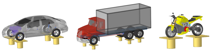
Input signals drive the posts to excite the vehicle. The vehicle’s response in the form of predicted loads and accelerations may be used to assess durability and ride.
The input signals driving the posts can be displacements or forces and moments. The signals may be synthesized or come from testing. In addition to the standard outputs for this event, the loads for any vehicle components can be output as needed for durability analysis.
Sequence of Actions Performed for an nPost Event
This section describes the sequence of actions performed by MotionView and MotionSolve when you run the event.- MotionView
-
- Converts any input signals that are accelerations to displacement signals and saves the signals to a CSV file in the same folder as the acceleration data file.
- Deactivates the AutoTire systems.
- Writes the model to the solver input file. The solver input file references the input signal files rather than containing the signals.
- MotionSolve
-
- Performs a static simulation on the vehicle during which the vehicle’s longitudinal, lateral and yaw motions, the steering input, and each wheel's spin rotation are locked.
- Unlocks the input signal files.
- Reads the input signal files.
- Runs a dynamic simulation from time=0.0 to the end time, using Akima’s method to interpolate the input signals.
Note:- If the input selected is Force/Moment and the ‘Add Wheel Reaction Forces’ option is checked, the reaction forces are evaluated on the tires and applied to the wheels.
- The event end time is automatically set to the end of the input signal data, if the current simulation end time is less than the time block in the input signal data.
Post Types
- Wheel Posts
- When you add an n-Post event, the event adds a wheel post for each Tire it finds in the model and attaches the Tires to their corresponding posts.
- Auxiliary Posts
- Auxiliary posts may be used to include excitations other than the road surface, such
as aerodynamic forces.
- Attachments for each Auxiliary Post consist of Body, Apply to Point and Mount
Point.Note: The direction of the Displacement/Force application is from Mount Point to Apply to Point.
- The post is connected using Ball Joints at both ends, to the Body on which the Force/Displacement is applied and to the Body on which the post is mounted (Ground Body).
- Attachments for each Auxiliary Post consist of Body, Apply to Point and Mount
Point.
Properties
- References
- Three Joints are used to constrain the vehicle when the event is simulated.
Name Description Vehicle Body Attachment used to constrain the vehicle during simulation. Steering Joint Attachment used to lock steering joint during simulation. Constraint 1 and Constraint 2 Optional attachments to hold the vehicle during static. These constraints are deactivated after static. - Perpendicular Axes Joint between the Vehicle body and ground body. This constraint is used only in the static simulation and deactivated during the transient simulation.
- Inline Joint between the Vehicle body and ground body. This constraint is used only in the static simulation and deactivated during the transient simulation.
- The Steering Wheel Joint is used to lock the steering wheel motion during the simulation.
- Settings
-
Name Description Vehicle Restraint Type of restraint used during the simulation. - Soft: A bushing is added between the Vehicle Body and Ground body.
- Hard: A fixed Joint is added between the Vehicle Body and Ground body.
- None: No restraint.
Coupling - Spindle: The wheel body is constrained at the wheel center to the vertical motion of the wheel post.
- Tire: A post shaker is attached to the wheel contact patch.
Signal Type Signal types for all Wheel posts. - Displacement
- Force/Moment
- Force/Moment is supported for Wheel posts with Spindle Coupling.
- If the ‘Add Wheel Reaction Forces’ option is checked, the reaction forces are calculated at the wheels, after the static simulation and added to the Z-direction force signal provided by the user for the Wheel post.
- Acceleration
- Acceleration is first converted to displacement, following which the displacement is applied.
Aux. Signal Type Signal types for all Auxiliary posts. - Displacement
- Force/Moment
- Acceleration
- Bushing Settings
- If the Soft vehicle restraint is selected in the settings, a bushing is added between the Vehicle Body and the Ground Body enabling the Bushing Settings option.
- Vehicle Orientation
- The vehicle orientation can be modified using the direction cosines of the marker in
this section to set the vehicle’s front and left vector.Note:
- n-Post event adds a post for each Tire in the model. These posts are added based on Vehicle Orientation. While adding the event, the Vehicle Orientation is detected based on the input from AltairDriver System. This orientation is used as reference for all the constraints, markers, and force/ moments in the n-Post event.
- If the orientation specified in the AltairDriver is the desired one, there is no need to make changes in n-Post orientation. However, after adding the n-Post event, if the vehicle orientation must change, the orientations in AltairDriver and in n-Post event panel should also be updated.
Post Settings
| Name | Description |
|---|---|
| Add Post | Brings up dialog to add posts (Wheel Post or Auxiliary Post). |
| Delete Post | Deletes the post selected in the Choose Post drop-down. |
| Data Directory | Location where the input signal files are stored, the drive files for posts shows the relative file paths with respect to this directory. |
| Choose Post | Choose the post for which the References and Data information is shown in the following sections. |
| Load Offset (Applicable for spindle coupling case and Force/Moments inputs) | This parameter offsets the force application point along the spindle axis by the specified value. Entering a positive value in this field, moves the point outboard. |
| References | Shows the attachments for the chosen post in Choose Post. |
| Spring Properties (Applicable for tire coupling case) |
|
| (X/Y/Z/RX/RY/RZ) Data | For Displacement and Acceleration signal types, X Y and Z directions can be
entered. For Force/Moment signal type, Force inputs in X, Y, Z directions and
moment inputs in X, Y, Z (RX, RY, RZ) directions can be entered.
|
Simulation Settings
- Analysis Parameters
- Define the numerical and output settings for the simulation:
Parameter Name Description Print interval The time step between successive outputs of simulation results. Real-Time Empowered When enabled, MotionSolve builds the FMU of the vehicle and solves it in real-time. Code generation When enabled, the C code for the MotionSolve Vehicle model excluding the driver and tire will be generated. This code can be used to compile and build an FMU, which can be used with any FMU compatible software. For more information see the Parameters: Simulation - Attributes topic.
- Dynamic Settings
- Defines the simulation control parameters for a time-domain-based nonlinear dynamic analysis. For more information see the Parameters: Transient Solver - Attributes topic.
- Static Settings
- Defines the solution control parameters for static and quasi-static analysis. For more information see the Parameters: Static Solver - Attributes topic.
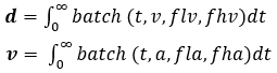
Conversion of Acceleration to Displacement
The measured acceleration signal is converted to displacement signal using the following relationship.
 |
Time series data |
 |
Integrated displacement signal from filtered velocity |
 |
Integrated velocity signal from filtered acceleration |
 |
Measured acceleration data |
 |
Batch filter applied in a band of filter frequency |
 |
Lower bound acceleration filter frequency, 0.5 Hz |
 |
Higher bound acceleration filter frequency, 1000 Hz |
 |
Lower bound velocity filter frequency, 0.5 Hz |
 |
Higher bound velocity frequency, 1000 Hz |
- Acceleration data is filtered with a batch filter between 0.5 Hz and 1000 Hz to remove DC offset in the data.
- The filtered data is integrated with respect to time, to generate velocity data.
- The velocity data is again filtered with a batch filter between 0.5 Hz and 1000 Hz.
- The filtered velocity data is integrated with respect to time, to get displacement data.
A file is written in the same directory as the data, with name as “{filename}_{channel}_disp.csv” with the first column as time and the second column as displacement data.
The generated displacement files are referenced in the XML file used by MotionSolve for the simulation.
Automated Output Report
| Report Name | Report Signals |
|---|---|
| Signal Type: Acceleration/Displacement |
|
| Signal Type: Force/Moments |
|