Mass/Inertia Setup
The Mass/Inertia Setup event is used to modify a specified body’s mass properties (mass, CG and optionally inertia tensor) to achieve a desired set of model (global) mass properties.
The event can be added to a vehicle model or any model that contains more than two body entities.
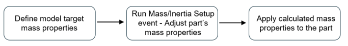
Sequence of Actions Performed in a Mass/Inertia Setup Event
- Initial Static Simulation
- Determines the model's mass, center of gravity (CG) location, and global inertia tensor.
- Iterative Adjustment Process
-
- Perform static analysis to derive the model’s initial mass properties.
- Compute differences between the model’s target and actual mass and CG.
- If differences are within a specified tolerance, keep the current part adjustment; otherwise, update part mass and CG.
- Assign updated mass and CG values to the specified body.
- Perform a new static simulation and re-evaluate differences.
- Repeat until differences fall within tolerance limits.
- Analytical Adjustment of the Part’s Inertia Tensor (if Inertia Adjustment is enabled)
-
- Perform a static simulation to obtain the actual model global inertia tensor.
- Compute the difference between the model’s actual and target global inertia tensor.
- Transform the differential tensor to the part's local coordinate system.
- Apply that differential tensor to the part’s local inertia tensor by adding differential tensor to part inertia tensor.
Note: If the part’s inertia tensor is mathematically invalid, inertia adjustment fails.
Properties
- Selectors - Body to Optimize
-
Name Description Body to optimize Attachment used to select the body whose mass properties are to be tuned. - Selectors – Steering/Wheel Joints to Lock
-
Joint Name Description Joint 1 (Optional) Attachment used to lock steering or wheel joint during simulation. Joint 2 (Optional) Attachment used to lock steering or wheel joint during simulation. Joint 3 (Optional) Attachment used to lock steering or wheel joint during simulation. Joint 4 (Optional) Attachment used to lock steering or wheel joint during simulation. Joint 5 (Optional) Attachment used to lock steering or wheel joint during simulation. Note:- As the group name suggests, these attachments are meant to be resolved for vehicle models. However, if you have any other model too, these optional attachments can be used to select the joints that you want to be locked, during the simulation.
- The Steering/Wheel Joints to Lock are optional. That is, you can resolve these joints only if you wish to have them locked during the simulation. Locking the free joints helps the solver in achieving equilibrium faster. These joints are auto-resolved for models that are built using the model library. You can clear the selections by using the Clear Joint Selections button.
- Model Target Parameters (in Global Frame)
-
Parameter Name Description Mass Target mass of the model. CG-x Target x coordinate of the global center of gravity (CG). CG-y Target y coordinate of the global CG. CG-z Target z coordinate of the global CG. Inertia Enables adjustment of the part’s inertia tensor. Ixx Target Ixx component of the global inertia tensor. Iyy Target Iyy component of the global inertia tensor. Izz Target Izz component of the global inertia tensor. Ixy Target Ixy component of the global inertia tensor. Ixz Target Ixz component of the global inertia tensor. Iyz Target Iyz component of the global inertia tensor.
Automated Output File
- Mass & CG Differences: Total mass and global center of gravity (CG) differences at each iteration.
- Final Inertia Tensor: The computed part inertia tensor and its validity status.
- Final Mass Properties: The calculated mass properties for both the overall model and the optimized body.
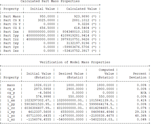
The first table displays the initial and calculated values of the body’s mass properties. You can apply the calculated values to the body in the model and perform a new Static Analysis. On solving, the model’s mass, center of gravity (CG) and inertia (if requested) are expected to match the target values.
The second table presents the model’s initial mass properties, the desired values, the computed results, and the percentage deviation between the desired and computed values.
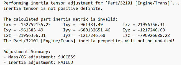
The calculated part inertia matrix is invalid, and thus the inertia adjustment fails.
Known Limitations:
Target values entered into the entity editor are those for a model at static equilibrium. The results from the optimization are the part’s CG, mass and inertia after a static equilibrium.
However, when you plug these values back into the model, the model is at design position in MotionView. Unless the design position is close to the static equilibrium position, the entered values may need further manual tuning to match the targets.
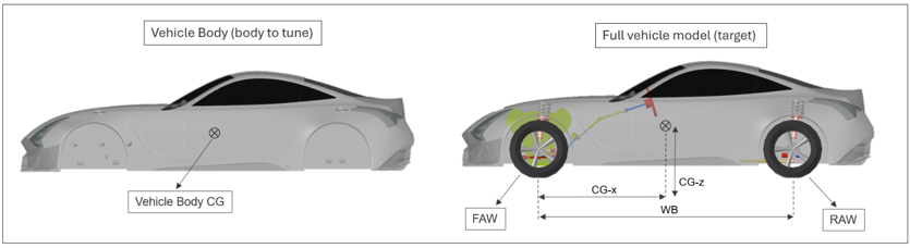
Example Application

 (assumed to be known targets)
To achieve these target mass properties for the entire model, the vehicle body’s mass properties can be adjusted accordingly using the Mass/Inertia Setup.