Abaqus *PART and *INSTANCE Modeling
The complete set-up of Abaqus parts and instances format input files is supported.
Primary use cases:
- Import of a CAD geometry
- Import of an Abaqus parts and instances format input file
Import of a CAD Geometry
- Preference setting
- Upon opening HyperMesh, you can set the user
profile to Abaqus
Standard2D/Standard3D/Explicit via . Further, click Preferences in the
File menu and check the Part ID Management
option, as shown below.
Figure 1. 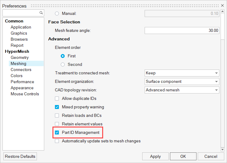
- Importing the CAD geometry and viewing in Part Browser
- Upon importing the CAD geometry with the Part ID Management preference
setting checked, you can open the Part Browser to
view the part and instance hierarchy.
Figure 2. 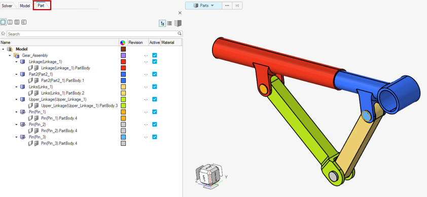
- Meshing Abaqus parts and instance format geometry
- Meshing parts individually is always recommended. When there are
multiple instances of the same part, it is crucial to mesh the first
instance of the part and synchronize the mesh to other parts. It is
always important to ensure that the part geometry that is meshed has the
mesh stored in its original component.
Figure 3. 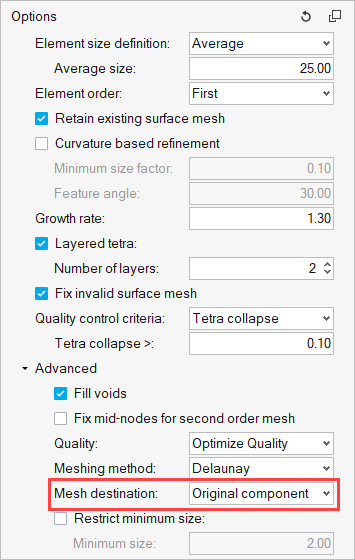
- Once the first instance of a part is meshed, a right-click option to
synchronize the mesh with other instances of the same part is available
in the Part Browser.
Figure 4. 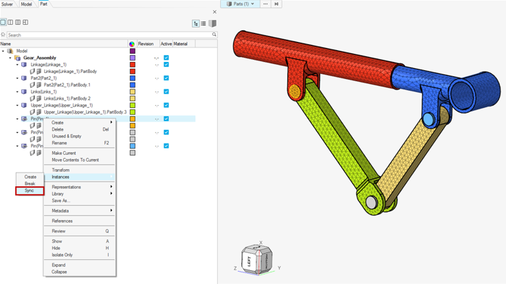
- Material
- Materials can be created in the Model Browser.
- Part content (Property, Sets, Surfaces, System, and so on)
- A double-click on any instance in the Part Browser will take it to an isolated part edit mode. Here, you can set up all the part content, such as a property with a material orientation system, sets, and surfaces that can be contained within a part. If the part has multiple instances in the model assembly, upon exiting the part edit mode, the changes and additions are automatically synchronized with other instances of the same part.
- It is only in this location that any part related content mentioned
above can be added in HyperMesh. A
right-click on the part in this mode will allow the creation of a
property and other part contained entities. Switching back to a
hierarchical part view or flat part view will automatically synchronize
the changes with other instances of the same part.
Figure 5. 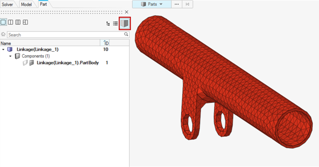
- Assembly and Root model content
- A right-click on Model allows a selection option to make the root model current. With the root model set as current, any surface, set, contact/tie, boundary conditions created using the Model Browser, panel, or any specific workflow tools like the Contact Browser creates entities in Assembly (outside of instances) or at root model (outside of Assembly) where it is relevant for the entity to remain.
- Analysis setup
- All the analysis conditions are a part of model level data (after *END ASSEMBLY). The corresponding model is set as current. Further, loads and boundary conditions can be created through panels with a load collector created for their use in the Model Browser. The Contact Browser is available to set up contact/tie between mating parts or components. Tie constraints created using the Contact Browser ensure that the keyword is placed at the Assembly level, as per the solver requirement. The analysis step can be defined using the loadstep manager. All these entities can also be created through the Model Browser or Solver Browser.
- Export
- Exporting a solver input file with Parts and Instances format requires
activating a checkbox in the solver export options, as shown below.
Figure 6. 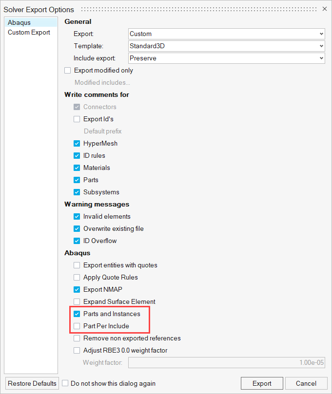
Import of an Abaqus parts and instances format input file
Unlike CAD geometry, an Abaqus parts and instances format input file can be directly imported using the solver import options. There is no need to turn on the Part ID management. Further set-up of any analysis conditions can be defined using the options discussed above.
Limitations and Restrictions
- Entities defined at the instance level are not supported.
- Does not support the creation or export of new include files. Include files from the imported input file are preserved and cannot be modified.
- Analysis set-up is restricted to the following:
- Entities such as sets and surfaces cannot be created or edited in an instance. The same entities can be created at the assembly or part level.
- It is highly recommended not to use panels for any set-up except for loads and boundary conditions.