Hexa (Contact)
This realization creates hexa elements between shell and/or solid elements connecting them with a tie contact definition.
General
- Tolerance
- Defines the search distance from the connector location.
- Layer
- Defines the number of links of the connection.
- Engineering Name
- Defines the physical representation of the realization.
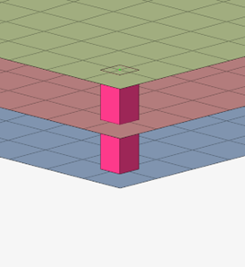
Weld Shape
- Hexa Number
- Defines the number of hexas to be created for each layer connection.
Figure 2. 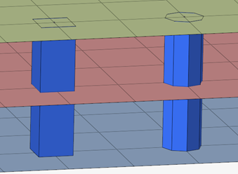
Realization Details
- Diameter Option
- Specifies the diameter definition. Can be a diameter mapping file or a real positive value.
- Diameter/Diameter Mapping File
- Defines the diameter of the realization.
Contact
- Creation
- Specifies how many contacts will be created depending on the number of links.
- Single Contact
- Specifies if the property created will be automatic or the sets will be user specified.
Legacy Realizations
The following realizations are replaced by Hexa (Contact):
- hexa (spot tie)
- mat100 (hexa)
- HC hexa spotweld