Connector Tools
Use the Connector tools to further define connections between components.
Connector Comparison Tool
Use the Connector Comparison tool to compare the connectors in your model to the ones in a Master Connection File (MCF) or Master Weld File (MWF).
From the Connector ribbon, click the arrow next to the Create tool set name and select Comparison from the drop-down menu.
MCF connectors display on the left, model connectors display on the right.
Connectors are displayed with their thicknesses, locations, distances, and so on in two grids: one for the MCF and one for the current model. These lists of connectors are compared based on connector ID, and any connectors containing a discrepancy are highlighted. However, you can specify a location tolerance to allow for small discrepancies in connector location.
In addition, a third grid displays the difference in distance between the model's connectors and the MCF connectors, and a fourth displays the results (pass/fail or notes/warnings).
You will be alerted if any discrepancies found
Tool Options
| Option | Action |
|---|---|
| Export |
Save the comparison as a comma-separated value (*.csv) file, which can be imported into spreadsheets and similar programs. |
| Zoom |
Zoom in on a connector by clicking an entry in one of the grids and then clicking this button. |
| Filter |
Hide all connector entries in the grids except for errors and any entry that you have specifically highlighted. |
| Show All |
Remove any filters previously applied. |
| Import MCF | Either type in the path to the Master Connection File or Master Weld File that you wish to compare the model to, or click the browse (open-folder) button at the end of the text field to browse to and select the file. |
| Thickness | Display each connector’s thickness in the MCF and Model grids. |
| PID | Display the part IDs of each connector's attached components in the MCF and Model grids. |
| Exclude from run check | Ignore thickness discrepancies, and/or ignore the PID numbers of the components attached to each connector (relying instead purely on the connectors’ X,Y,Z values to determine discrepancies) when comparing connectors. |
| Location tolerance | Do not report an error for the connectors whose locations do not match between model and MCF but in which the discrepancy is this distance or less. |
| Run Check | Run a comparison between the model’s connectors and the ones listed in the MCF/MWF file after you have specified an MCF or MWF file and the desired thickness and PID criteria. |
| Reset All | Clear the grids and reset the checkboxes and Location Tolerance to their default states (does not clear the MCF file path). |
| Close | Close the Connector Comparison tool. |
Connect Components with RBE3s
Create RBE3s for connecting structures.
-
From the Connectors ribbon, Tools tool group, click the
RBE3 tool.
Figure 1. 
- Optional:
From the guide bar, click
 to adjust the tolerance, connectivity options, and weight factor
calculations.
to adjust the tolerance, connectivity options, and weight factor
calculations.
- Connectivity option
- All, Faces, and Closest
- Weight Factor
- Inverse Distance, Normal Distribution, and Equal to
- RBE3 organization
- Automatic (default) and ManualNote: Select Manual to choose from the guide bar the Target Component (or Target Part while in the Abaqus solver interface) where the RBE3 is going to be organized.
Figure 2. RBE3 Tool Guide Bar with RBE3 Organization Manual 
Figure 3. RBE3 Tool Options Menu 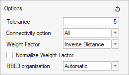
- Select the independent node.
- From the guide bar, click Components to pick the component to connect the independent node to.
-
Click Create.
Figure 4. 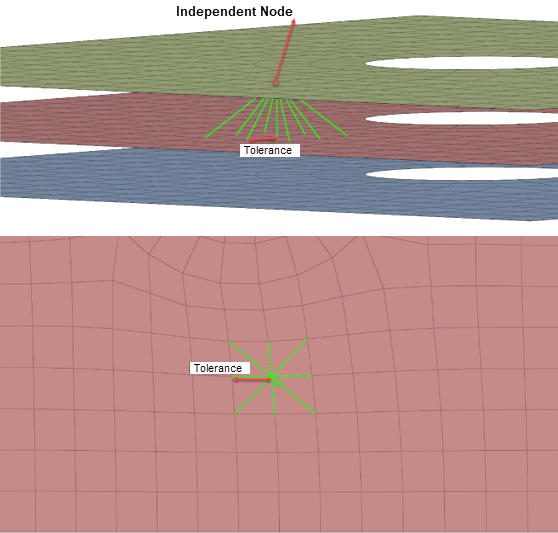
Imprint Nodes and Points on Connectors
Imprint nodes and points as significant points on connectors.
-
From the Connectors ribbon, Tools tool group, click the
Imprint tool.
Figure 5. 
-
From guide bar, click to adjust the tolerance.
The tolerance for projecting the node/point to the connector must be large enough so that the distance from the farthest node to the connector is smaller than the tolerance.
- From the drop-down menu, select Nodes or Points to select nodes or points on the model.
-
From the guide bar, click
Connectors to select the connector(s).
Figure 6. 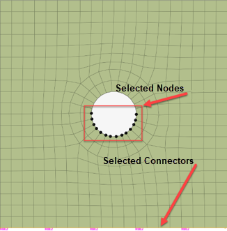
- From the guide bar, click Imprint.