Apply Mass
Create a dummy connector entity to add mass to a part, or create areas of mass to represent parts not present in the CAD or FE data.
-
From the Connectors ribbon, click the arrow next to the Create tool group and
select Appy Mass.
The Connector Apply Mass dialog opens.
-
Select entities.
Option Action Location Entity Select the FE or geometric entities to which the mass connector entities are created. - Nodes
- Connector entities are created at the locations defined by selected FE nodes.
- Points
- Connector entities are created at the locations defined by selected geometry points.
- Connectors
- Mass is applied to existing connector entities, so you can update applied masses by updating the connector.
Link Entity Select an entity type to which the mass is applied. - Nodes
- Mass is applied via nodes. When this option is chosen, nsm becomes unavailable in the mass type field.
- Elements
- Mass is applied to the nodes of elements.
- Components
- Mass is applied to the nodes of entire components.
- Tags
- Mass is applied to nodes via their tags.
- Assemblies
- Select the assemblies to be added as link entities.
-
Define apply mass options.
Option Action Connect Method Select a method to determine which entities the mass connector connects. - Proximity
- Connect entities to any entities of the location type within the search tolerance.
- User Select
- Manually select entities.
Mass Type Select a mass configuration. - nsm
- The mass is a non-structural mass and
defines/updates the required solver
cards.Note: Only available for OptiStruct and Nastran solver interface.
- Point Mass
- Mass is a single mass element created at a node.
- Rigid Mass
- Mass takes the form of a mass element connected to nodes with rigid elements (multiple RBE2).
- RigidLink Mass
- Mass takes the form of a mass element connected to nodes with a rigidlink element (single RBE2).
- RBE3 Mass
- Mass takes the form of a mass element connected to nodes with a RBE3 element.
Mass The amount of mass you wish to add. Note: The functionality of this option is dependent on your selection for the distribution option. Mass can be the total mass, the mass per node, or the mass per unit of area (such as square millimeter).Type Solver card to be created. Note: Only available when mass type is set to nsm.NSM Entity Type Assign a NSM entity type attribute to the connector to be created. Note: Only available when Mass Type is set to nsm.This attribute will be written into the connector and is considered during the next realization.
Upon creation of nsm connectors, the FE data (nsm group entity) is realized and a new component (CE_Mass_inc_<include name>) is created inside the current include. The newly created connectors will reside in this new component. Each include is meant to host its own CE_Mass_inc_<include name> component, and a warning will display if the component name already exists in a different include. This helps ensure that unrealizing and rerealizing nsm connectors will keep the FE data in its original include.
The realization routine always looks for the content (elements) of the links and investigates whether they exclusively reference the same properties (direct or indirect) and can be condensed clearly in property references in the NSM group.
The realization can behave differently depending on this check and the defined NSM entity type attribute.- Elements
- The realization creates one element based NSM group for each connector. All of the connector-referenced elements are listed by ID in the created NSM group.
- Property
- The realization creates one NSM group per connector. If all of the connector-referenced elements can be exclusively condensed in clearly defined properties, theses properties are used for the property-based NSM group.
Mass Distribution Choose how to apply the amount specified in the mass= field to the affected location's nodes. Note: Only available when the Mass Type is set to Point Mass.The examples below all use a 9-node array with a 100mm x 100mm area (for example 10,000 square mm) and a mass of 10 grams.- Apply To All Nodes
- The mass is applied repeatedly, once to each
node (so the total mass applied is the mass times
the number of nodes).
Figure 1. Mass (10) Applied to Each Node 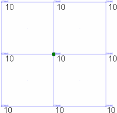
- Divide Mass By Nodes
- The mass is divided by the number of nodes, and
the result applied to each node.
Figure 2. Mass (10) Divided Among 9 Nodes 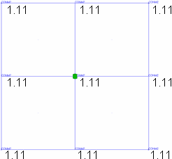
- Divide Mass By Area
- Divide the mass= value among the affected
nodes.Note: Only available when the connect what option is not set to nodes.This method ensures that non-uniform meshes still produce uniform mass distribution.
- Determining the mass per unit of area (in this example, 10g/10,000mm=0.001g/sq. mm).
- Determining the area of each element (in this case, all of the 4 elements are 50x50=2500 sq. mm).
- Multiplying the per-unit mass by the number of units per elem to find each element's total mass. (.001x2500=2.5g per elem in this example).
- Dividing the elem's mass by the elem's number of nodes (yielding 2.5/4=0.625 per node in this example).
- Nodes belonging to more than one element receive a per-node mass from each element accumulatively.
Figure 3. Each Node Receives 0.625 Grams 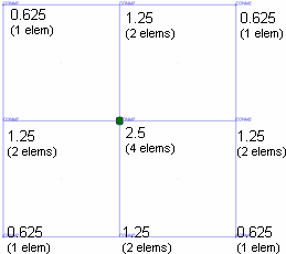
- Unit Area Distribution
- Apply the full mass= value to each square unit
of the selected area, then distribute this mass
across the area as for divide mass by area (steps
2+). In other words, this follows the same steps
as described for divide mass by area with the
omission of step 1, so that the full mass= value
is used as the per-unit mass. This method produces
an area-based distribution but with much higher
masses.Note: Only available when the connect what option is not set to nodes.
Figure 4. Each Node Receives 6,250 Grams. This method produces an area-based distribution with much higher masses. 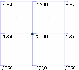
- Click Create.