Connector Quality Check
Use the Quality controller to perform various checks on connectors and realized FE.
The Quality controller is used to determine if the model contains duplicate connectors or if the realized elements meet the quality requirements such as the length of 1D elements and their perpendicularity to the shells they connect.
-
Open the Quality controller one of two ways:
- Right-click in the Connector Browser and select from the context menu.
- From the Connector ribbon, click the arrow next to the Create tool set name and select Quality from the drop-down menu.
- Select connectors to consider.
-
Select a check type and define any options.
Check Type Check and Fix Action Duplicates Removes duplicate connectors (according to the ID Manager selected option). Combine Combines all adjacent connectors into one connector that connects all the link entities. Find Too Long - Find Too Short - Find Too Long or Short - Find Too Close to Edge Moves connectors found along the surface they are on, by the required distance to satisfy the specified tolerance. Collinearity -
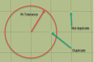
Duplicates
Finds all duplicate connectors (two or more connectors that are located within the set tolerance and connect the same link entities (Parts) are considered duplicates).
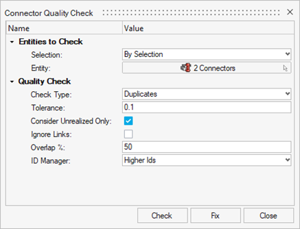
- Selection
- Determines whether the check will be performed on all connectors/attachments, or on a selection of connectors/attachments.
- Entity
- Connector or Attachment entity selection.
- Tolerance
- Specifies the distance between two or more connectors to be considered duplicate.
- Ignore Links
- Do not take links into consideration during check (number of links, linked entities and so on).
- Overlap %
- Specifies the percentage of overlap for two or more connectors to be considered duplicate (Field appears for Line/Spot Line Connectors only).
- ID Manager
- Determines which connector(s) will be deleted with the Fix action.
- Fix
- Deletes the duplicate connector(s) according to ID Manager.
Combine
Finds all adjacent connectors (two or more connectors that are located within the set tolerance and connect different parts/components).
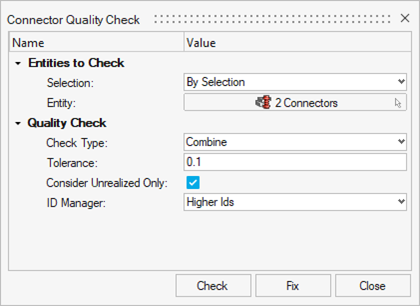
- Selection
- Determines whether the check will be performed on all connectors, or on a selection of connectors.
- Entity
- Connector entity selection.
- Tolerance
- Specifies the distance between two or more connectors to be considered adjacent.
- ID Manager
- Determines which connector(s) will be discarded with the Fix action.
- Fix
- Combines the adjacent connectors according to the ID Manager.
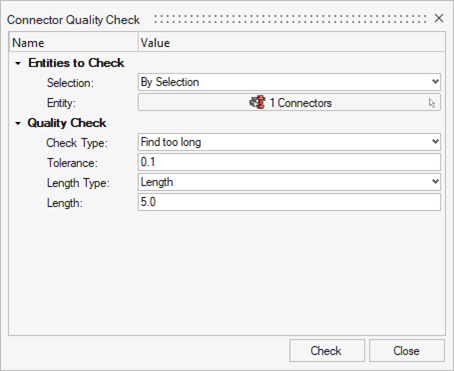
Find Too Long
Finds all connectors whose length exceeds the length specified by the set tolerance.
- Selection
- Determines whether the check will be performed on all connectors, or on a selection of connectors.
- Entity
- Connector entity selection.
- Tolerance
- Specifies the deviation from the “correct” length.
- Length Type
- Specifies whether the average thickness of the links or a user defined value will be used.
- Length
- A user defined value as the “correct” length.
Find Too Short
Finds all connectors whose projection length falls short of the specified length by the set tolerance.

- Selection
- Determines whether the check will be performed on all connectors, or on a selection of connectors.
- Entity
- Connector entity selection.
- Tolerance
- Specifies the deviation from the “correct” length.
- Length Type
- Specifies whether the average thickness of the links or a user defined value will be used.
- Length
- A user defined value as the “correct” length.
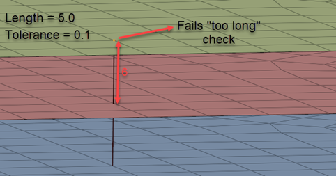
Find Too Long or Short
Finds all connectors that deviate from the specified length, by the set tolerance.
- Selection
- Determines whether the check will be performed on all connectors, or on a selection of connectors.
- Entity
- Connector entity selection.
- Tolerance
- Specifies the allowed deviation from the “correct” length.
- Length Type
- Specified whether the average thickness of the links or a user specified value will be used.
- Length
- A user defined value as the “correct” length.
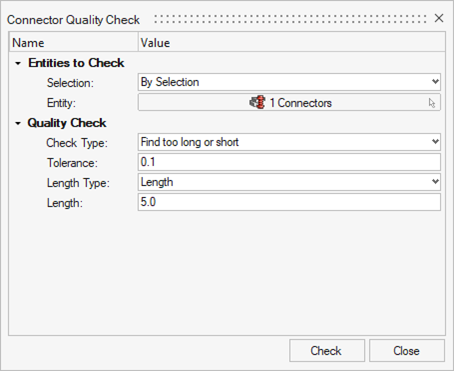
Find Too Close to Edge
Finds all connectors whose distance to a free/feature edge is smaller than the set distance.
- Selection
- Determines whether the check will be performed on all connectors, or on a selection of connectors.
- Entity
- Connector entity selection.
- Feature Type
- Determines whether a feature edge, a free edge, or both will be considered during the check.
- Feature Angle
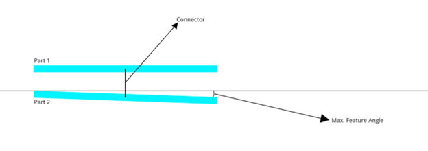
- Specifies the maximum angle between elements to be considered a feature.
- Distance
- Specifies the distance from the free/feature edge(s).
- Fix Action
- Moves the connectors away from the free/feature edge(s).
Collinearity
Checks if the links of a connector are parallel to each other, considering the Max Feature Angle. If the first check is satisfied and the Diameter is used, a check is performed to ensure that the parallel area is big enough for a realization with the set diameter.
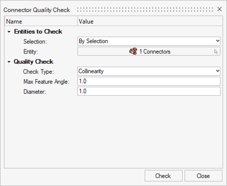
- Selection
- Determines whether the check will be performed on all connectors, or on a selection of connectors.
- Entity
- Connector entity selection.
- Max Feature Angle
- Specifies the maximum angle between the links of a connector to be considered parallel.
- Diameter
- Specifies the diameter of the realization that needs to fit in the parallel area.