Define Connector Controls
Use the Control Manager to create and edit the various types of controls that will be used later when realizing connectors.
-
From the Connectors
ribbon, click the Controls tool.
Figure 1. 
- Optional:
At the top of the dialog, click
 to open an .hm binary file that
contains saved connector controls, or click
to open an .hm binary file that
contains saved connector controls, or click  load in an FE_Config file.
- Use the tabs to cycle between controls for each group.
-
Right-click and select Create then edit the
following.
- Name
- Describes the realization in terms of its real-life representation, such as a resistant spot weld or a self-piercing rivet.
- Type
- The Finite Element realization that is representing the engineering entity.
- Engineering Name
- A mechanism to organize by a defined set or categories outlined by the xMCF (χMCF) format.
Tip: Right-click on a control to duplicate or delete it. -
Select a control then use the right side of the dialog to manage how the
control will be realized.
Multiple controls can be selected and edited simultaneously. The parameter list will be filtered, leaving only the common fields available to edit.
- Optional:
At the top of the dialog, click
 to save the defined controls to your active folder,
or click
to save the defined controls to your active folder,
or click  to save the controls to a folder of your
choice.
to save the controls to a folder of your
choice.
- Click OK.
General Options
Overview of the general connector options.
- Solver
- The specific solver that the control is configured to.
- Tolerance
- The search distance the connector uses for a projection.
- MCF (Master Connection File)
- The MCF the connector was imported with.
- System (Point/Fastener Only)
-
- No system
- Do not create a system during realization.
- Single system
- Create one system for the whole realization.
- 1 sys per layer
- Create one system per layer during realization.
- 2 sys per layer
- Create two systems per layer during realization.
- Name
- A free field for Naming the connector so it is easier to identify.
- Engineering Name
- A pre-defined list of Engineering types from the xMCF schema.
Pitch Options
Overview of the general pitch options.
- Pitch Option
-
- Pitch
- Create a connector realization at regular intervals of a specified distance.
- Density
- Create a specified number of realizations that are equally distributed between the significant points. If the value is lower than the significant points, realizations are created at each of the significant points.
- Distribution Option
-
- Linear
- The distribution of the significant points are linear (the distance between each significant point is constant).
- Exponential Bias
- The distribution of the significant points is set according
to an exponent.
- NL Biasing Value
- Specifies where the transitional area is biased. For example, 10 indicates bias in the intermediate area, whereas 0.1 indicates bias in the start/end area.
- Run In Length
- The length of the transitional area between the Start/End Pitch and the Internal Pitch.
- Start Length/End Length
- Start Length and End Length are the lengths that the Start Pitch and End Pitch affect, respectively.
- Start Pitch/End Pitch
- Start Pitch and End Pitch are the pitch values of the Start Length and End Length, respectively.
- Internal Pitch
- The pitch value of the intermediate area (between the start and end lengths).
- Single End
- The End Length and End Pitch options are removed, and the Internal Pitch affects the whole of the remaining length.
Figure 2. 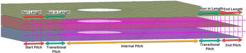
- Retain Nodes
- Create realizations at the input node locations. For geometrically defined connectors, the connector tries to identify a node path.
- End Offset Option
-
- Half Spacing
- Offset the start half the pitch distance (or calculated density distance).
- Input
- Enter the start and end offset values.
Weld Shape Options
Weld shape options are specific to certain connector types. For more information see Realizations.
Realization Options
Overview of the general realization options.
- Diameter
- This field is used for realizations where the size of the realized element is created based on the diameter value, or for realization types where the diameter is defined in the property cards.
- When you have weld nuggets from hexa patterns (more than one hexa), the
diameter is measured from two opposite nodes.
Figure 3. Hexa 
Figure 4. Weld Nugget 
-
- Diameter
- Specify a single diameter value.
- Diameter mapping file
- Obtain diameter values that you assigned to a range of flange thicknesses in the Diameter Table.
- Along with flange thickness ranges, you can also specify the
main flange thicknesses to consider when assigning diameter
values.
Figure 5. 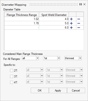
- Skip Welding (Line Connector Only)
- Creates a line connector with alternating weld pieces and gaps. The option takes the Pitch and Density values, along with the weld length, and break length to break the connector into segments. If the Density is used, the density number needs to be greater than the number of segments in the weld or the connector will fail to realize. Significant points are ignored when using Skip Welding.
Connectivity Options
Overview of the general connectivity options.
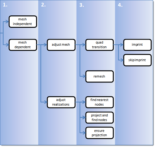
- Mesh Independent
- The connector realizes independently from the mesh. Use for realizations which do not need any mesh changes, and the connection is primarily defined via a solver-specific card or the nodes which need to be connected are defined by a cylinder, such as Bolt (cylinder spring) for Radioss.
- Mesh Dependent (Point/Line/Area Options)
-
- Adjust Realization
- The realization is adjusted depending on the adjustment method defined below. The mesh is not modified, at the expense of non-normal or incomplete realizations. Many realization types are defined with head elements attached to body elements. In the case of these realization types, the head elements realize the connection without modifying the mesh, and the body elements are created in a normal direction.
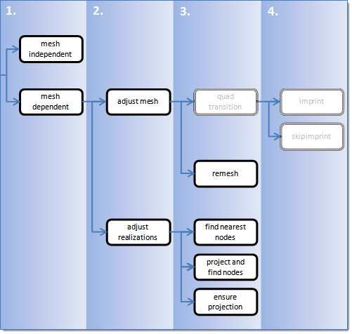
- Adjust Mesh
- The mesh is adjusted to the projections; there are a few different imprinting options. The realizations are identical between the mesh independent and mesh dependant adjust mesh options.
Contact Options
Overview of the general contact options.
- Creation
-
- Single Contact
- Create a single contact for all realizations of the same type.
- One Contact Per Link
- Create a contact per link.
- One Contact Per Link Pairing
- Create a contact for all links in the connector.
- Card Image (LS-DYNA Only)
- The type of card image to set to the contact definition.
- Single Contact
-
- Automatic
- Create sets/groups.
- User Control
- Select the main and seondary set.
HAZ Options
HAZ options are specific to certain connector types. For more information see Realizations.
Property and Material Options
Overview of the general property and material options.
- Property/Material Creation
-
- Single
- Create a property/material for the whole realization of the same type.
- Link pair
- Create a property/material per link pairing.
- Per connector
- Create a property/material for the whole realization per connector.
- Logical connection
- Create a property/material by all the links on the connector.
- Script only
- Use a pre-defined script that creates properties, materials, contacts, and assigns attributes to the realization. The connector only creates the elements; everything else needs to be created and organised via the script. This can only be defined within the fe_configuration file as a *post.
- Property (Only available for Single and Per Connector)
- Choose a property. If left unspecified, a property is created.
- Material (Only available for Single and Per Connector in Explicit solvers)
- Choose a material. If left unspecified, a material is created.
- Direct Property Assignment
- Assign the property/material directly to the element definition.
- Customization Script
- Unless set to Script Only, the connector completes the realization with any of the property/material options above. The Customization Script option then places all connectors that refer to the same script onto a mark. The script then has to process those connectors in the mark to achieve the desired result.
- Method Type
-
- None
- No calculation methods are performed during the realization process.
- Huth /User Define Huth
-
- Coefficient
- A table of coefficients for the Huth calculation method.
- Material Option
-
- Select from Model
- Select a material from within the model to use for a Young’s modulus.
- Select from File
- Select a material from a file to use for a Young’s modulus.
- E value
- Describe Young’s modulus directly.
- Connection Type (Huth Only)
- The default coefficient values.
- K4/K5/K6
- Stiffness values for the rotational degrees of freedom.
- A/B1/B2 (User Defined Huth Only)
- Allow user coefficient definitions.
Behavior Options
Overview of the general behavior options.
- Link Option (Line/Area)
-
- Closest
- Uses the links closest to the connector by distance.
- Adjacent
- Uses the links adjacent to the connector.
- Two links only
- Selects only two links from the connector links.
Figure 8. 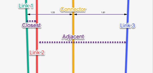
- Project Control Methods
-
- Normal to links
- Connector calculates a normal projection to all links.
- Along discrete direction
- Input a direction for the projections for all links.
- Normal to closest link
- Find the closest link first, then do normal projection to it, then use this direction to project to the rest of links.
- Normal to furthest link
- Find the furthest link first, then do normal projection to it, then use this direction to project to the rest of links.
- Normal to specified link
- Specify a link, then do normal projection to it, then use this direction to project to the rest of links.
- Flange Condition
- When selected, the connector limits the projection to a normal (88° – 92°). When turned off, the connector searches within a 360°. For hexa realizations, it changes the order the connector projects to determine the number of projections.
- Use 2nd Projection
- Uses the solver projection logic function to position the nodes on the surface of the elements.
- Solid Outer Face
- When realizing with solids, determine if the realization is on the inner face of the solid or through the solid.
- B/L classification angle
- The angle to determine if the connector is a Butt weld or a Lap weld.
- L/T classification angle
- The angle to determine if the connector is a Lap weld or a T weld.
- Snapping to Edge
-
- Snapping to Edge L/Snapping to Edge T/Snapping to Edge B
- Try to position the realization to the edge of the linked part depending on the weld type.
- Collector Name Prefix
- An optional field to push a defined name to.
- Auto Trim (Area)
- Automatically trims the connector area realization where no projection
exist.
Figure 9. Area Connector, locations without projection 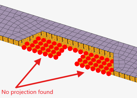
Figure 10. Realized Area Connector with Auto Trim ON 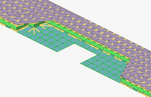
- Auto Trim (Line Only)
- Automatically trim the connector line when realizing.
- Partial Realization Percentage (Point Only)
- Allow points along the connector to not realize and still mark the connector realized.
- Partial Imprint Percentage (Line Only, Mesh Dependent Quad Transition options)
- Allow the imprint to not fully succeed along the connector and still mark the connector realized.
- Imprint Options (Mesh Dependent Quad Transition options)
-
- Preserve Washer
- Controls how washers are preserved during the seam imprint realization.
- Do Not Share Zone Elements (Line Only)
- Seam imprint allows heat affected zones (HAZ) to be merged in close areas. In this situation, one element might touch the weld elements from two different connectors. Do not share zone elements prevents zone elements from being shared.
- Quad In Corner (Line Only)
-
- Double Quad corner/Single Quad corner
- Controls whether a single or double element is created in corners of quad seam connectors with a certain vertex.
- Corner Angle
- An angle must be defined for a single quad corner. If the corner angle is greater than the defined angle, a double quad corner is created.
- Quad Size Reduction %/ Quad Skew Degrees (Line Only)
- Controls the maximum deviation from the perfect quad element for the heat affected zone (HAZ). It can be controlled, if the element size or the element skew is more important to retain.
- Sliver Elements: (Line Only)
- Sliver elements are small elements that you may not want in your model. In the images below, a perfect perpendicular projection resulted in sliver elements. The Sliver Elements setting can be used to manage sliver elements in your model. In the images below, the red elements represent the HAZ elements.
- Feature Angle
- Determines important features to retain during the imprint. Features that cross the HAZ, as well as nearby features cannot be retained.
- After Imprint
- Remesh or rebuild the surrounding mesh after imprint for better mesh flow and quality .
- Seam Test Points Alignment (Line Only)
- A global option. If the seam connectors are close, by activating “Seam Test Points Alignment” option in the connector Entity Editor, the test point alignment is based on the proximity of other connectors to get better mesh flow. It also ensures the cross-over connector should have a common test point so that unique nodes are created.
- Unrealize Remesh or Rebuild
- Remeshes or rebuilds HAZ elements and the elements surrounding it upon connector unrealization. Option is available only when unrealize remesh or rebuild is set to Remesh or Rebuild. Number of layers to be considered around HAZ elements for remesh or rebuild can be controlled with user input value for the layers.
- Unrealize Remesh or Rebuild Layer
- The number of elements considered to remesh or rebuild.
- After Imprint (Fastener Only)
- During realization, if the mesh is altered to realize the connector, this option allows you to select between "Remesh" and "Rebuild" meshing algorithms.
- Rebuild Washer (Fastener Only)
- Perform a rebuild operation on the created washer in cases where the washer is close to a feature edge. This will potentially change the shape of the washer to snap to feature edges to avoid poor mesh quality.
- Unrealize Fill Hole Created (Fastener Only)
- If the control is set to "create hole if none”, this fills the created hole when the connector is unrealized, returning the surface back to its original configuration before realization.
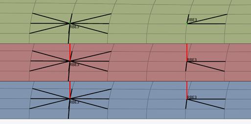
Rbe3 Radius
Every point realization that uses RBE3 elements as the head, had the Rbe3 Radius option available, which can change the number of independent nodes.
Options
- Rbe3 Radius
- Defines a circle with the specified diameter within which all nodes will be connected to the RBE3 as independent nodes.
- Rbe3 Radius Center
- Specifies whether the center of each RBE3 will be considered individually or the RBE3 cluster center will be used (for Hexa (Rigid) only).
- Feature Angle
- Defines the angle at which nodes will stop being considered in the RBE3.
- Rbe3 Weight Factor
- Specifies the weighing method for the RBE3s.
- Inverse distance
- The distance from the center of the RBE3 to a node, is inversely proportional to the weight that will be assigned to that node.
- Normal distance
- The distance from the center of the RBE3 to a node, is proportional to the weight that will be assigned to that node.
- Equal
- The weight that will be assigned to the RBE3 node is equal to the value you have specified.
- Normalize Rbe3 Weights
- Specifies if the weights of the RBE3s will sum up to 1.