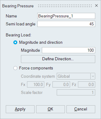
Bearing Pressure
![]()
This tool is used to distribute the given load on nodes in cylindrical face, which fall in the given Semi Load Angle from the loading direction using cosine function.
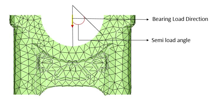
The semi load angle interpretation is as shown below.
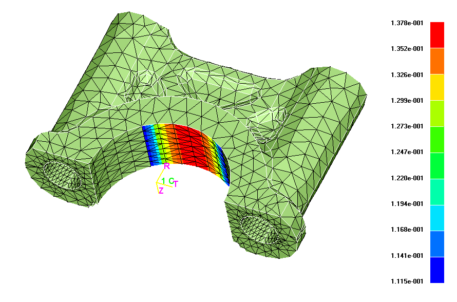
Once the bearing pressure is defined, contour plot can be visualized as shown below, using the Show Contour option in the Pressure object / Bearing pressure object in the LBC Browser.
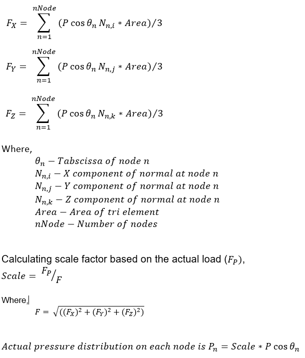
Methodology
Pressure "P" is assumed and the force distribution over the nodes, which fall inside the given Semi Load Angle from the loading direction is calculated using the cosine function. Components of total force for the assumed pressure "P" for TRI element face are calculated as shown below.