Contact
![]()
This tool is used to define contact between bodies, faces and edges.
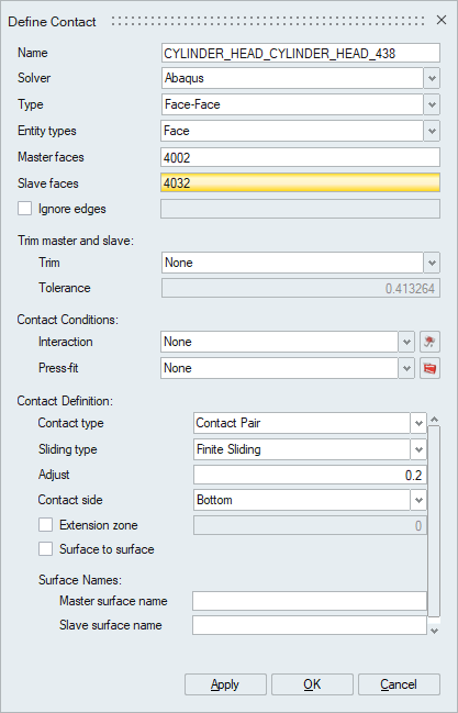
Define Contact
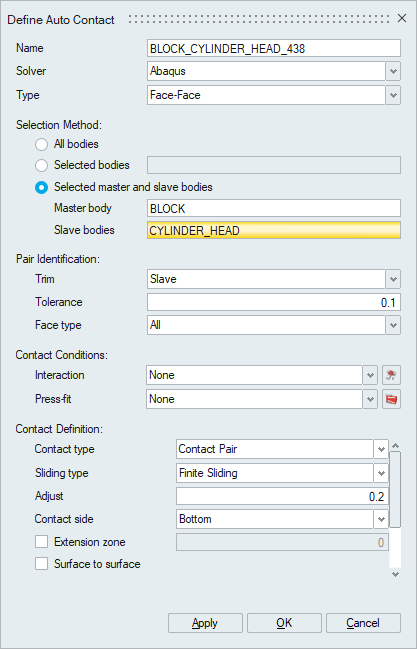
Manual contact creation. Contact will be applied on the selected master and slave entities.Auto Contact
- All bodies: Contact will be created for all the bodies available in the model/solution.
- Selected bodies: Contact will be created only for selected bodies.
- Selected master and slave bodies: Contact will be created for selected master and slave bodies.
Description
- Key features of this tool are
- Feature based contact pair identification. Planar and Cylindrical contact pairs between bodies can be separately identified.
- Automated file-based contact creation.
- Contacts present in the model can be reviewed using Query Contact or Contact Manager options.
- Supports contact parameter definition for the following solvers
- Abaqus
- OptiStruct
- ADVC(ADVENTURECluster)
- Nastran
- Ansys
- Permas
- RADIOSS
- SimLab uses MasterBodyName_ SlaveBodyName naming convention for contacts by default. Duplicate names are avoided by appending numeric values. However, we can modify the default names.
- Body based contact creation automatically identifies overlapping faces within the specified tolerance and based on the contact face type - Planar / Cylindrical / All. Only one master body can be specified whereas slave bodies can be many.
- Set based contact creation is used to select solid element face set /
surface set / node set and create contacts between them. All the elements /
nodes that are part of the sets will be included in the respective surfaces,
tolerance checks, face type and trimming are skipped in this method. Set
based contact creation is supported for OptiStruct, Abaqus, ADVENTURECluster
and Permas.
Set based contact creation
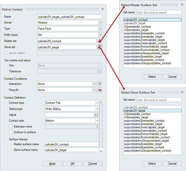
- The master set name and the slave set name will be assigned as the master surface and slave surface names respectively.
- The surface that is used as a slave in one contact cannot be used in other contacts.
- The set selection dialog has a name filter option to search and select the names easily.
- Node set is supported only for the secondary surface definition for OptiStruct contact.
- The ignore edge option is used to select the edges of the slave surfaces whose elements have to be ignored in contact creation. It is mainly used to avoid including slave nodes of contact surface in multiple contact definitions. This support is available for Abaqus and Permas.
- The contact surface elements will be trimmed based on following trim option
selected
- None option includes all the elements of both the master and slave faces.
- Slave option includes only the slave elements which are obtained by projecting the elements of master face on to the slave face.
- Slave and master option will project both the slave and master elements over each other, then the trimmed slave and master elements are used for contact creation.
- Surface interaction can be used to refer to surface behavior, friction coefficient and pressure-closure relationship for structural analysis. In case of thermal analysis, it is used to refer conductance, clearance and temperature correlation.
- Press-fit is used to define clearance/interference condition for contact pairs.
- General contact is used to define the contact for all bodies in the analysis. There is no need to select bodies for defining the contact. Solver will automatically detect the surfaces from the bodies which are come in contact and apply the user defined contact surface properties to those surfaces.
- The Ignore bodies option in the General contact is used the exclude the selected bodies from the automatic contact creation.
- Currently, General contact is supported for OptiStruct (Explicit dynamic analysis/Drop Impact), Radioss and Abaqus solvers.
Guidelines for master and slave surface identification
- The surface with finer mesh should be the slave.
- The smaller surface should be the slave.
- The softer surface should be the slave.
Solver Dependent Parameters
Solver Dependent Contact definition file format
SimLab allows user to create and reuse contact definitions based on Body / Node Set / Element Set / Group / GROUP_NUMBER_TEMPLATE. This improves modelling robustness and consistent definitions of contact to avoid errors.
Body Method
This method is used to create contact between the bodies. The body names should be defined in a specific format.
There are two methods user defined or automatic detection of master and slave.
- User defined master and slave
Master Master Body Slave Slave Body - Automatic detection of master and slave
The determination is based on the contact face area and number of elements as per the above mentioned guidelines.
Sample definition file for Body Method -> Auto detectionNote: Support only for two bodiesBodies Body1, Body2
Group Number Template Method
This method is used to create contact based on group names. The group names should be defined in a specific format to use this method.
In this method the master and slave group names should follow certain syntax and the contact definition information identifies the slave group and master group, and creates contact between them.
- The slave group name should follow the template "Pair_<Number>_<User
Text>" and master group name should follow the template
"Pair_<Number+1>_<User Text>".
- The first text "Pair" is used to identify the contact parameters for that contact.
- The second text "<Number>" is used to identify the slave and master surface group. The even numbers will form the slave group and the next corresponding odd number will be the master group.
- The "<User Text>" will be used to add additional information in contact surface names. This can be ignored if not required.
- A sample slave name and master name would be Pair_1000_BoltBlock and Pair_1001_BoltBlock.
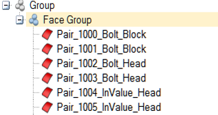
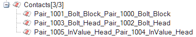
The above groups will result in creation of three contacts.
Contact Right Click options
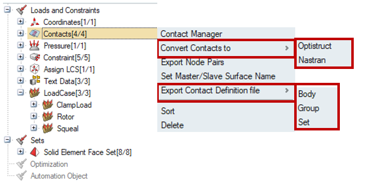
- Contact Manager groups the contact based on contact type and lists all the contact parameters in a tabular form.
- Convert Contacts to
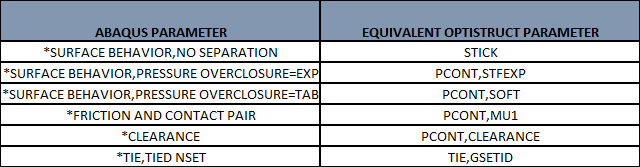
- Optistruct: will convert the contact solver parameters to OptiStruct contact as per below image.
- Nastran: will convert the contact solver parameters to Nastran contact. Currently the contacts will be converted to Nastran glue contact.
- Export node pairs option is used to export contact surface node ids along with its coordinate position to a separate text file.
- Set Master / Slave surface name option opens a separate dialog to define surface names for contact surfaces.
- Export contact definition file option is used to
export the contact information defined in the model to a text file called
the Contact definition (*.dat) file.
- The Body option will create a contact definition file based on body names.
- The Group option creates a contact definition file based on group name defined in the contact faces.
- The Set option creates a contact definition file based on set names. Set based contact is supported only for Abaqus contacts.
- The Import Contacts option available at right click of Loads and constraints in Loads and constraints browser is used to import the contact definition file and create contacts.
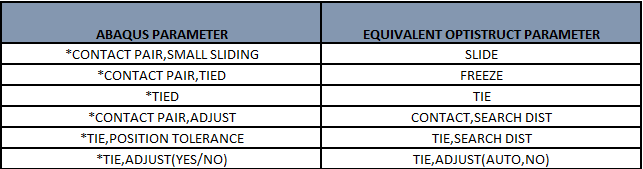
Abaqus to OptiStruct conversion parameters
Conversion Table:
If Surface interaction and pressfits are defined:
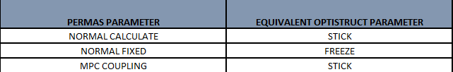
Permas to Optistruct conversion parameters