Kinematics and Compliance
The Kinematics and Compliance (K&C) test is performed by applying a range of forces at the two contact patches of a half-vehicle model to determine the suspension’s characteristics. The motion of the wheel caused by the force application is measured and recorded during this event. This in turn helps to determine suspension hard point locations, spring rates, bushing rates, arm lengths, and so on.
Introduction
Detailed Description
- Ride
- Roll
- Contact patch force
- Steer analysis
- Ride
- The event begins with the ride analysis wherein all wheels are subjected to a
vertical displacement input through the jacks. The inputs have the same amplitude as
those that are in phase. This part of the event lasts for 10 seconds.
Time in Seconds Action 0 to 2.5 Wheels move from Design Position to Jounce Position. 2.5 to 5.0 Wheels move from Jounce Position to Design Position. 5.0 to 7.5 Wheels move from Design to Rebound Position. 7.5 to 10.0 Wheels move from Rebound Position to Design Position. 10.0 Event Ends. - Roll
- This event begins immediately after the ride event is complete. For this part of the
event all wheels are subjected to a vertical displacement input through the jacks. The
inputs amplitude is the same and with the left and right wheels being out of phase by
180 deg. This part of the event lasts for a duration of 10 seconds.
Time in Seconds Action 10 to 12.5 Left Wheels move from Design Position to Jounce Position. Right wheels move from Design Position to Rebound Position.
12.5 to 15.0 Left Wheels move from Jounce Position to Design Position. Right wheels move from Rebound Position to Design Position.
15.0 to 17.5 Left Wheels move from Design Position to Rebound Position. Right wheels move from Design Position to Jounce Position.
17.5 to 20.0 Left Wheels move from Rebound Position to Design Position. Right wheels move from Jounce Position to Design Position.
20.0 Event Ends. - Contact patch force
- This event begins after the roll analysis is completed. This phase of the event
evaluates the compliance of the suspension by simulating forces at the contact patch.
For the first 20 seconds of this event, a lateral force is applied at the contact
patch. The lateral force simulates cornering conditions. For the next 20 seconds, a
longitudinal force is applied at the contact patch. The longitudinal force simulates
braking and acceleration conditions. The third part of this event simulates moments
about the wheel's axes by applying a torque about the wheel vertical axis. This part
of the event lasts for 20 seconds again.
Time in Seconds Action 20 – 30 Lateral force is applied on all contact patches in a parallel direction. 30 - 40 Lateral force is applied on all contact patches in an opposing direction. 40 - 50 Aligning torque about the vertical axis (Global Z) is applied on all contact patches in the same direction. 50 – 60 Aligning torque about the vertical axis (Global Z) is applied on all contact patches in the opposing directions. 60 – 70 Longitudinal force is applied on all contact patches along the positive X direction of the Global Origin to simulate a braking condition. 70 – 80 Longitudinal force is applied on all contact patches along the negative X direction of the Global Origin to simulate an acceleration condition. 80 Event ends.
- Steer analysis
- This final part of the kinematics and compliance analysis involves testing the front
suspension kinematics when a steering input is applied. This part of the event lasts
for 10 seconds with steering motion applied in both directions.
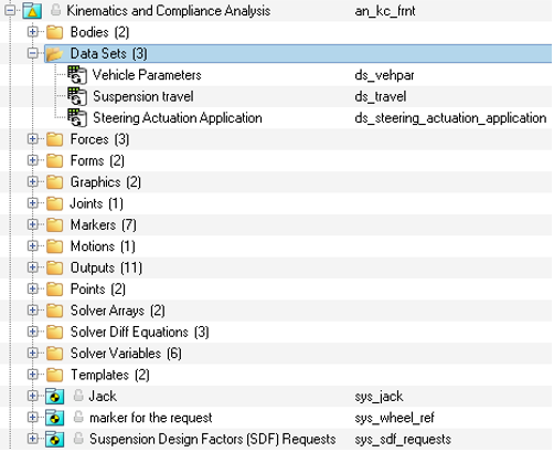
Time in Seconds Action 80 – 85 Steering motion is applied in the counter-clockwise direction. 85 – 90 Steering motion is applied in the clockwise direction. 90 Event ends. - The entities in the event are displayed in the MotionView
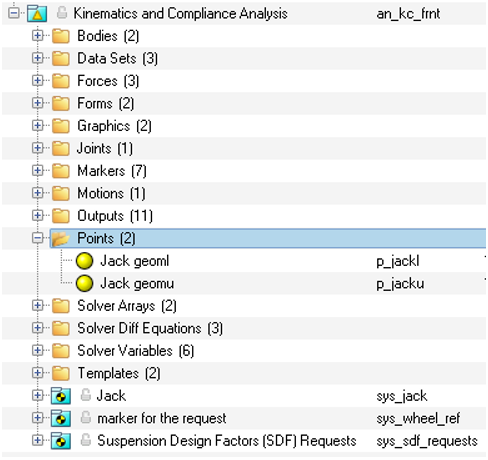
Model Browser as shown in the image below:
Figure 2. Browser View - Kinematic and Compliance Analysis 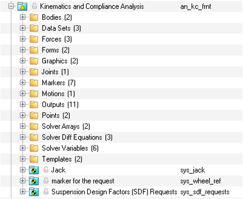
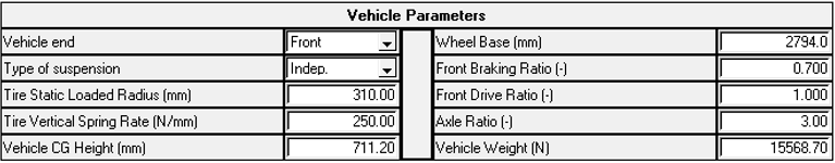
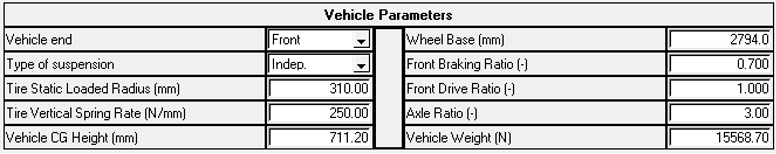
Input Parameters
| Name | Description |
|---|---|
| Vehicle End | Choose “Front” for Front suspension. And “Rear” for rear suspension. This information is used in calculating Suspension Design Factors (SDF). Available options are: Front and Rear. |
| Type of suspension | Option that needs to be set based on the suspension type. This information is used in calculating Suspension Design Factors (SDF). Available options are: independent and dependent. |
| Tire Static Loaded Radius (mm) | The radius of the front tire with the vehicle weight acting on it. |
| Tire Vertical Spring Rate (N/mm) | The spring rate of the tire. The value is used for computing certain outputs and needs to match the value in the tire property file when using force-based tires. |
| Vehicle CG Height (mm) | The vertical distance from the vehicle CG body CG to the ground. |
| Wheelbase (mm) | The longitudinal distance between the front and rear wheel center. |
| Front braking ratio | Front braking ratio The brake force distribution at the front wheels. A value of 1 indicates 100% braking on the front. |
| Front drive ratio | The ratio of engine power distributed to the front axle. A value of 1 indicates all power is sent to the front axle. |
| Axle ratio | The ratio between the angular velocity of the input gear to the angular velocity of the output gear. It is also commonly known as gear or speed ratio of the axle’s differential. |
| Vehicle Weight (N) | Total weight of the vehicle expressed in Newtons. |
| Name | Description |
|---|---|
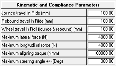
| Jounce travel in ride (mm) | The vertical input distance for the wheels to travel in the upward direction relative to the ground in ride. |
| Rear rebound travel in ride (mm) | The vertical input distance for the rear wheels to travel in the downward direction relative to the ground in ride. |
| Wheel travel in roll (jounce and rebound) (mm) | The vertical input distance for the wheels to travel in both directions relative to ground. |
| Maximum lateral force (N) | The sideways force applied at the wheel contact patch to simulate conditions experienced during cornering. |
| Maximum longitudinal force (N) | The force applied along the length of the vehicle at the wheel contact patch to simulate braking and acceleration. |
| Maximum aligning torque (Nmm) | The torque applied about the wheels vertical axis. |
| Maximum steering angle +/- (Deg) | The rotational input at the steering wheel to simulate cornering. |
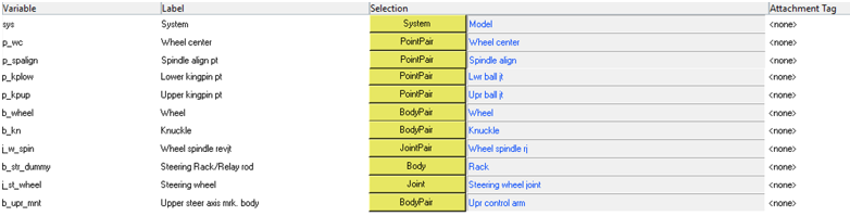
Attachments
| Name | Description |
|---|---|
| System | System where the analysis is located, usually the model system. |
| Wheel Center | Attaches the wheel center pair points. |
| Spindle align pt | Attaches the pair points used as reference for the spindle alignment. |
| Lower kingpin pt | Attaches the pair points used as the lower kingpin point. |
| Upper kingpin pt | Attaches the pair points used as the upper kingpin point. |
| Wheel | Attaches the wheel pair bodies. |
| Knuckle | Attaches the knuckle pair bodies. |
| Wheel spindle revjt | Attaches the pair revolute joints used to constraints the wheel bodies. |
| Steering Rack / Relay rodRack jt | Attaches the to the translational joint at the rack body of the steering for a rack and pinion steering system. |
| Steering wheel | Attaches revolute joint of the steering wheel used to apply the steering rotational motion. |
| Upper steer axis mrk. Body | Attaches the body pairs used to define the upper steering axis marker. |
Datasets
The Kinematics and Compliance analysis contains three datasets. The Vehicle Parameters and Suspension Travel take the vehicle and simulation parameters as input (as described in the tables under Input Parameters). The dataset Steering Actuation Application takes information related to the steering motion/force application point and the axis along (or about) which the motion/force is applied. This is used in locking the steer motion when compliance matrices are extracted for SDF calculations.
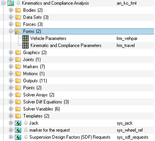
Forms
| Form | Description |
|---|---|
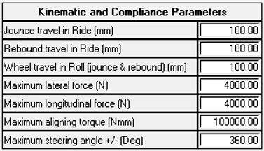
| Kinematics and compliance parameters | This form should be used to define the simulation conditions such as jounce and rebound distance, steering angle, the contact patch forces, and so on. |
| Vehicle Parameters | This form should be used to define the vehicle conditions such as its weight, CG height, wheelbase, vertical spring rate, and so on. |
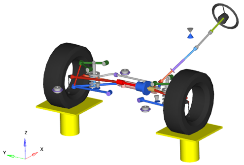
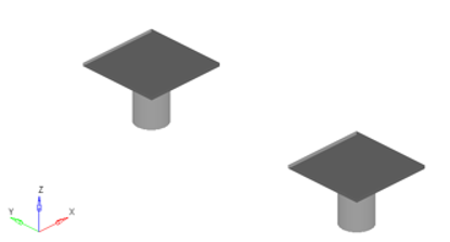
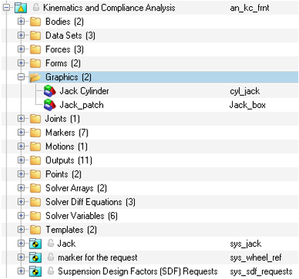
Graphics
The kinematics and compliance analysis consists of two graphics entities to represent the two jacks up on which the vehicle is hoisted with the two tires being in contact with the jack.
| Name | Type | Description |
|---|---|---|
| Jack Cylinder | Cylinder | Represents the cylindrical column for the jack. |
| Jack Patch | Box | Represents the square platform for the jack. |
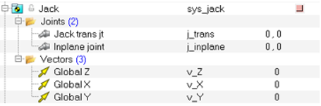
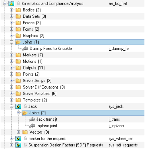
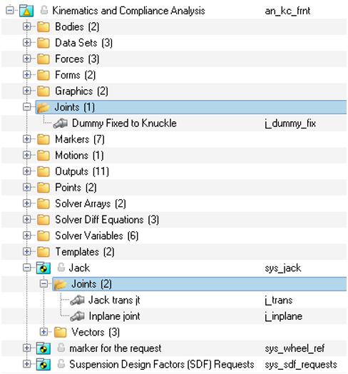
Joints
The kinematics and compliance analysis contains three joints. Two of these are in the Jack sub-system.
| Name | Type | Description |
|---|---|---|
| Dummy fixed to Knuckle | Fixed | Connects the dummy body located at the contact patch to the knuckle body and is located at the wheel center. |
| Jack trans jt | Translational | Connects the jack body to the ground body and is aligned along global Z. |
| Inplane joint | In plane | Connects the wheel to the jack body and is located at the contact patch. |
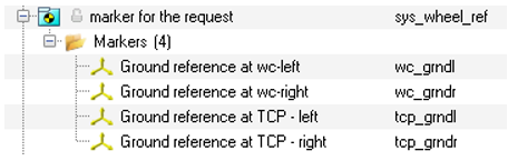
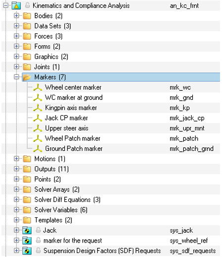
Markers
| Name | Description |
|---|---|
| Wheel center marker | This marker is defined on the dummy bodies and is located at the wheel center. The test rig parameter array refers to this marker. |
| WC marker at ground | Marker is defined on the ground body and is located at the wheel center. The test rig parameter array refers to this marker. |
| Kingpin axis marker | Marker is defined on the knuckle, is located at the lower ball joint, and is aligned with the upper ball joint. The test rig parameter array refers to this marker. Used for geometric computation of the steer axis. |
| Jack CP marker | Marker is defined on the Jack and is located at the Jack upper point (Jack geomu) referring to the tire contact patch. |
| Upper steer axis | Marker used for geometric computation of the steer axis. |
| Wheel patch marker | Marker is defined on the wheel and is located at the wheel patch. The marker is used by the patch force entity. |
| Ground patch marker | Marker is defined on the ground body and is located at the Jack upper point (Jack geomu). |
Points
| Name | Description |
|---|---|
| Jack geoml | Point that locates the bottom of the jack. The point is referenced by the jack translational joint. |
| Jack geomu | Point that locates the top of the jack. The point is also used as the tire contact patch point and referenced by the jack forces, joints, markers, outputs, and graphics. |
Solver Variables
| Name | Description |
|---|---|
| Left Feedback variable | Contains the expression that calculates the Global Z Displacement of the left wheel center marker, relative to the original location of the left wheel center, in the global coordinate system. |
| Left Command variable | Contains the expression for ride and roll phases of the analysis for the left wheel. The expression is explained in detail below this table. |
| Right Feedback variable | Contains the expression that calculates the Global Z Displacement of the right wheel center marker, relative to the original location of the right wheel center, in the global coordinate system. |
| Right Command variable | Contains the expression for ride and roll phases of the analysis for the right wheel. The expression is explained in detail below this table. |
| Steering Feedback variable | Contains the expression that calculates the Global Z Angular Displacement of the steering wheel, relative to the original location of the steering wheel center, in the global coordinate system. |
| Steering Command variable | Contains the expression for steering phases of the analysis. The expression is explained in detail below this table. |
- Left Command variable
-

Figure 15. Wheel displacement left based on the solver variable expressions 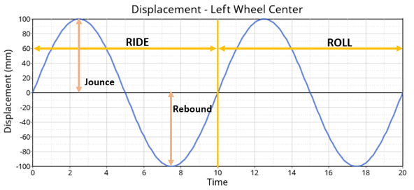
- Right Command variable
-
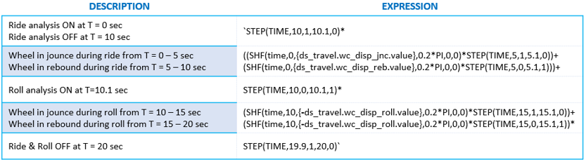
Figure 16. Wheel displacement right based on the solver variable expressions 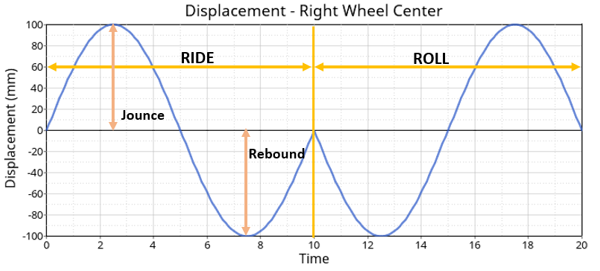
- Steering Command variable
-
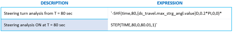
Figure 17. Plots – Wheel Displacements for all four wheels based on the solver variable expressions 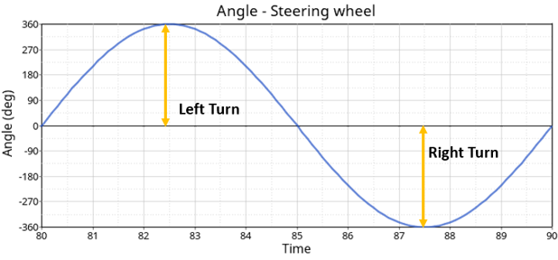
Figure 18. Model Browser View - Solver Variables - Kinematics and Compliance Analysis 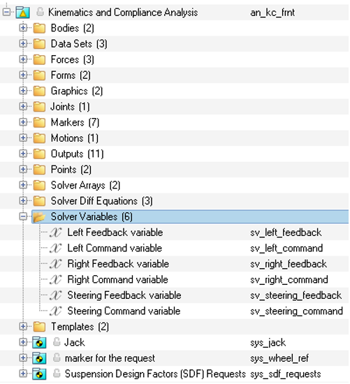
Solver Differentials
| Name | Description |
|---|---|
| Diff Left Jack | Contains the expression that is used by the left jack actuation force. |
| Diff Right Jack | Contains the expression that is used by the right jack actuation force. |
| Diff Steering | Contains the expression that is used by the steering actuation torque. The expression is explained in detail after this table. |
- Diff Left Jack expression in detail
- The structure and logic for the three solver diff expressions are similar, the only
difference being that they each use their respective solver variable values. The below
uses the “Diff Left Jack” as an example:
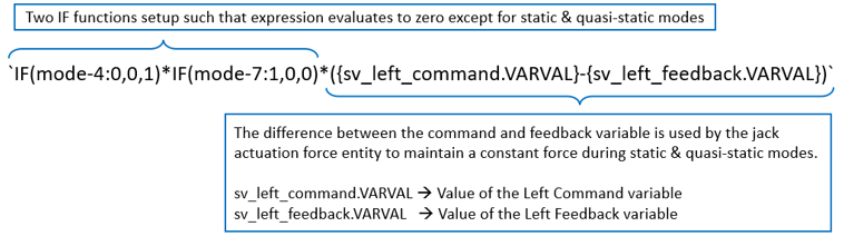
Figure 19. Model Browser View - Solver Differentials - Kinematics and Compliance Analysis 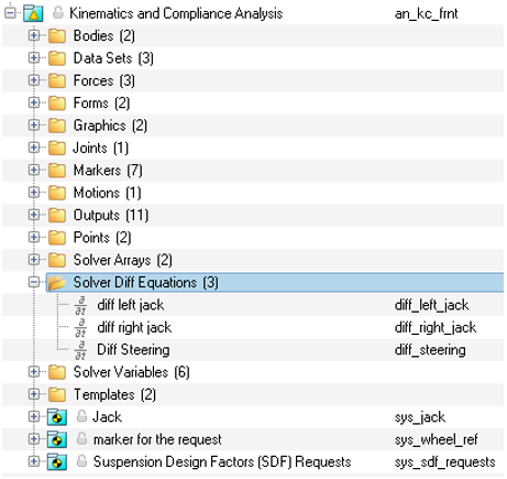
Solver Array
- Vehicle Parameter array
- The Vehicle Parameter array contains vehicle information that is used to calculate
the SDF’s. Some of the data is also used in the analysis events to create point
locations and forces. The data is entered in the Vehicle Parameter Form.
Vehicle Parameter Array Element Name Description Use Ds_vehpar.veh_end.ival Vehicle End 1 ➔ front suspension
2 ➔ rear suspension
3 ➔ 2nd rear suspension
Communicates the suspension type to the SDF subroutine. The subroutine calculates different values for certain parameters depending on which end of the vehicle is being analyzed. Ds_vehpar.dif_mnt.ival Differential Mount type 0 ➔ mounted to body
1 ➔ Unsprung mount (integral with the axle)
Used in the SDF calculations in the anti-lift and anti-dive calculations. Ds_vehpar.tire_slr.value Tire Static Loaded Radius in mm Used to locate the “Jack GeomU” point and in many of the SDF calculations. Ds_vehpar.tire_rate.value Tire Spring Rate in N/mm Used in the SDF calculations. Ds_vehpar.cg_height.value Vehicle CG height, measured from ground to the CG in the Z direction (mm) Used in the SDF calculations (especially the Anti-lift and anti-dive calculations). Ds_vehpar.wheel_base.value Vehicle Wheelbase (mm) Ds_vehpar.front_brake.value The Ratio of front brake torque to total brake torque (typically 0.6 to 0.7) Ds_vehpar.front_drive.value The ratio of the engine torque applied to the front axle divided by total torque Ds_vehpar.axle_ratio.value The nominal Axle ratio of the suspension being analyzed (typically in the range 2.7-5.0) Ds_vehpar.veh_weight.value Total Vehicle Mass in Kg
- Testrig Parameter Array
- The testrig parameter array contains point, force and motion data, and is passed to the SDF subroutine and used to run the SDF calculation event. The testrig parameter array is symbolically defined and should not require editing.

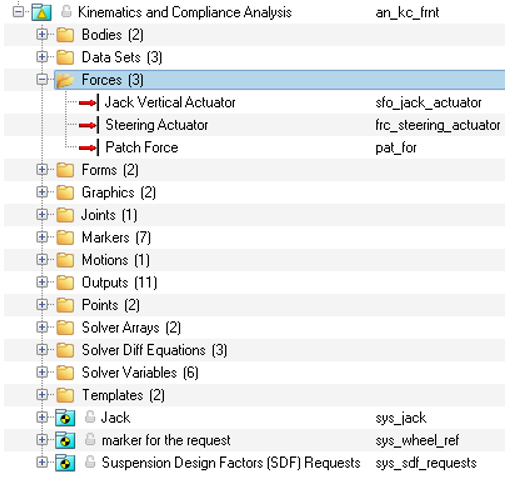
Force
| Name | Description | |
|---|---|---|
| Jack Vertical Actuator | This is an Action Reaction force pair which acts on
the jack and is reacted on ground in the vertical direction. The force is a DIF()
that points to the SolverDiff ID’s for the Left and Right Jacks. When the DIF is evaluated during statics and quasi-statics, the derivative of the Solver Differential Equation is set to zero. The result is that a Force is generated by the DIF that forces the measured wheel displacement to follow the command wheel displacement. |
|
| Steering Actuator | This is an Action Reaction torque which acts on the steering wheel and is reacted on vehicle body in the steering wheel alignment direction. The torque points to the SolverDiff which ensures that the right amount of torque is applied to rotate the steering wheel such that the desired steer angles is achieved. Desired steer angle is provided in the solver variable “Steering Command variable”. | |
| Patch Force | This is an Action Only force pair applied at the
wheels contact patch with the wheel patch marker as reference to simulate
longitudinal, lateral, and aligning forces. The forces for each direction are defined using expressions as listed below. |
|
| Fx - Left |
The expression contains a simple harmonic function that applies a sinusoidal force input, whose value is defined in the KnC Parameter Dataset, at a frequency of 0.1PI between 60 to 80 seconds. |
|
| Fy - Left |
The expression contains a simple harmonic function that applies a sinusoidal force input, whose value is defined in the KnC Parameter Dataset, at a frequency of 0.2PI between 20 to 40 seconds. |
|
| Fz – Left | 0 | |
| Tx – Left | 0 | |
| Ty – Left | 0 | |
| Tz – Left |
The expression contains a simple harmonic function that applies a sinusoidal torque input, whose value is defined in the KnC Parameter Dataset, at a frequency of 0.2PI between 40 to 60 seconds. |
|
| Fx - Right |
The expression contains a simple harmonic function that applies a sinusoidal force input, whose value is defined in the KnC Parameter Dataset, at a frequency of 0.1PI between 60 to 80 seconds. |
|
| Fy - Right |
The expression contains a simple harmonic function that applies a sinusoidal force input, whose value is defined in the KnC Parameter Dataset, at a frequency of 0.2PI between 20 to 40 seconds. For the first 10 seconds between 20 – 30 seconds, the force is positive Y direction and negative Y for the next 10 seconds. This is done to simulate parallel and opposing lateral forces with respect to the left wheel. |
|
| Fz – Right | 0 | |
| Tx – Right | 0 | |
| Ty – Right | 0 | |
| Tz – Right |
The expression contains a simple harmonic function that applies a sinusoidal torque input, whose value is defined in the KnC Parameter Dataset, at a frequency of 0.2PI between 40 to 60 seconds. For the first 10 seconds between 40 – 50 seconds, the torque is in the same direction as the left wheel and opposite to it for the next 10 seconds. This is done to simulate parallel and opposing aligning torques with respect to the left wheel. |
|
Joints
The kinematics and compliance analysis contains three joints.
| Name | Description |
|---|---|
| Dummy Fixed to Knuckle | Fixed joint pair that attaches the knuckle to the dummy body and is located at the wheel center. |
| Jack trans jt. | Translational joint that attaches the jack to the ground body and is located at the Jack geoml point. |
| Inplane joint | Inplane joint that attached the wheels to the jack and is located at the Jack geomu point (tire patch location). |
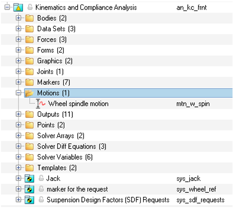
Motions
| Name | Description |
|---|---|
| Wheel spindle motion | Wheel spindle motion provides the lock between the wheels and the spindles and prevents the wheels and tires from rotating. |
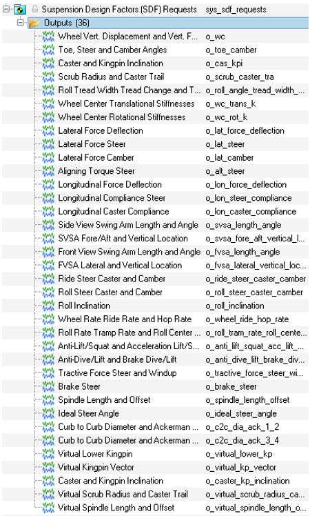
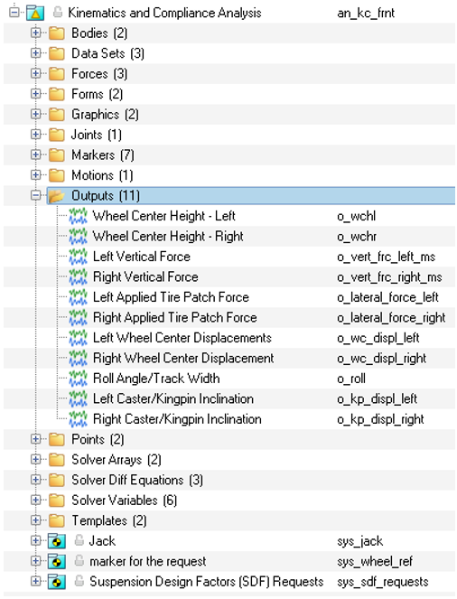
Outputs
The kinematics and compliance analysis consists of a total of 47 output entities. They can be broadly classified in to two groups: Static design factor outputs (SDFs) and non-SDFs.
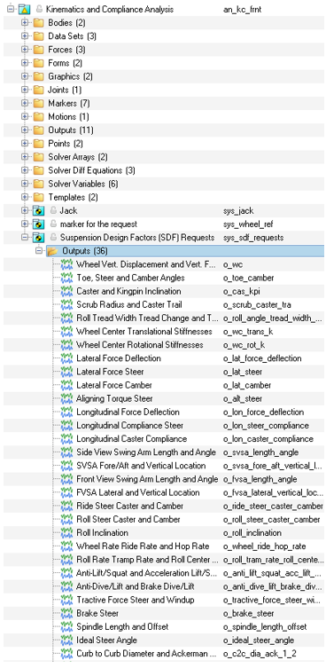
| Name | Description |
|---|---|
| Wheel Center Height – Left | Measures and outputs the displacement between left wheel and the left jack in the global reference frame. |
| Wheel Center Height – Right | Measures and outputs the displacement between right wheel and the right jack in the global reference frame. |
| Left Vertical Force | Measures and records output for the force at the Inplane joint-left in the global reference frame. |
| Right Vertical Force | Measures and records output for the force at the Inplane joint-right in the global reference frame. |
| Left Applied Tire Patch Force | Measure and outputs the force at the left tire contact patch in the global reference frame. |
| Right Applied Tire Patch Force | Measure and outputs the force at the right tire contact patch in the global reference frame. |
| Left Wheel Center Displacements | Measures and outputs the displacement between the left front wheel and the ground body in the wheel center marker reference frame. |
| Right Wheel Center Displacements | Measures and outputs the displacement between the right front wheel and the ground body in the wheel center marker reference frame. |
| Roll Angle / Track width | F2 ➔ Computes the roll angle using the expression:F3 ➔ Computes the track width using the
expression: |
| Left Caster/Kingpin inclination | F2 ➔ Computes the Caster angle of the left
wheel:F3
➔ Computes the Kingpin Inclination of the left
wheel: |
| Right Caster/Kingpin inclination | F2 ➔ Computes the Caster angle of the right
wheel:F3
➔ Computes the Kingpin Inclination of the right
wheel: |
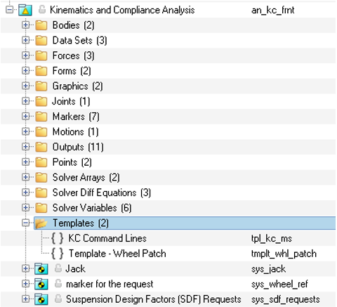
Templates
The kinematics and compliance analysis contains two templates.
The first template, KC Command Lines, defines the output file control statements, the static analysis blocks where entity states are modified, and simulation begin and end times specified.
The second template returns the Radial vector that points from the wheel center to the tire patch. This is used to locate the tire patch.
| Statement | Description |
|---|---|
|
This is a simple parameterization for evaluating and sending the solver commands to MotionSolve XML’s <command/> section. IF condition determines whether to continue after Ride/Roll analysis or not. |
|
The output block defines the result format and the files that the solver needs to generate. |
|
These two set of deactivate statements turn OFF the wheel motions that have been locking the wheels from moving. |
|
Performs a static simulation for 20 secs. |
|
The IF condition combined with the activate statements, turn ON the wheel motions, locking the wheels, after the simulation reaches 20sec, in other words after the simulation perform the Ride and Roll analysis. A static simulation then progress from 20s until the end time = {sim_time}, 90s for the Kinematic and Compliance analysis. |
|
Stops the simulation. |
Sub System
The kinematics and compliance analysis contains three sub-systems.