Four-wheel drive (4WD) vehicle models employ a power distribution mechanism between the
front and rear axles. This could be an open differential or a viscous coupling. In MotionView’s vehicle libraries, both options are provided.
1. Transfer Case
In MotionView’s Car/Small truck library, a viscous force is
used to drive the front and rear drive shafts. The type of mechanism can be chosen under the
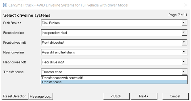
“4WD Driveline Systems” page while building the vehicle model through the wizard
selections:Figure 1. Transfer case options for a 4wd configuration
Once the model is built, the Transfer case is available under the Model Browser:Figure 2. Transfer case System in Model Browser
1.1 Transfer Case Model
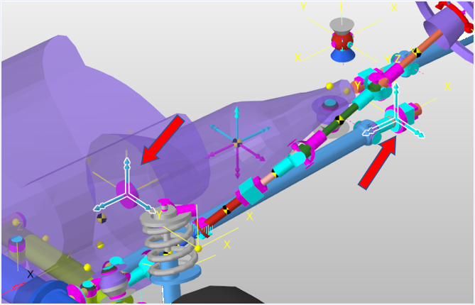
The transfer case is modeled using two Force entities: one on each drive shaft. The
torque magnitude is an expression which attempts to minimize the difference between the
rotational speeds of the front and rear drive shafts. This results in an almost equal
rotation. Figure 3.
Thus, the torque is a function of the following:
A constant or a penalty (CONST)
Rotational speed of the front drive shaft (OMEGA_FRONT)
Rotational speed of the rear drive shaft (OMEGA_REAR)
T = CONST * ( OMEGA_FRONT - OMEGA_REAR )
1.2 Transfer Case - Interface
The parameters of the transfer case, especially the coupler constant/rate can be
edited using a form provided in the Transfer case system:Figure 4. Interface for editing parameters
2. Transfer Case with Centre Differential
Transfer case with centre differential is the other option available while choosing the
power distribution mechanism for the 4WD vehicle. This model is based on an open
differential that transmits power from the engine to the two drive shafts. The model
consists of:
Differential Housing
Front Drive Gear
Rear Drive Gear
Centre differential
The power is transmitted to the drive shafts via two couplers:
Main shaft to centre diff: 2 joint coupler connecting the main
shaft and centre diff
Centre diff to drive shafts: 3 joint coupler connecting centre
diff – rear drive gear – front drive gear
2.1 Transfer Case with Centre Differential - Interface
The power ration between front and rear can be varied by editing the coupler ratios as
needed. It is important to use the correct signs and joint orientation directions to
ensure proper functioning of the central differential.Figure 5. Interface for editing centre diff based power transmission