Help
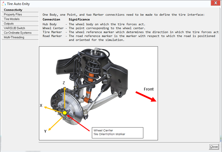
The Help button in the panel area can be used to quickly access information on AutoTire and the associated parameters. On clicking the Help button, the following window is displayed.

The following section reproduces some information available in the Help dialog.
Outputs
| Label | Description | Units |
|---|---|---|
| Radius | X- Deformed radius of the Tire | Length |
| Y- Actual Rotational speed of the tire | rad/time | |
| Z- Rotational speed considering Unloaded radius | rad/time | |
| LonSlip LatSlip IncAngle (ISO) | X- Longitudinal Slip of the tree | % |
| Y- Lateral Slip of the tree | rad | |
| Z- Inclination angle of the tire | rad | |
| Tire CP Forces (W- Axis system) |
Tire forces and moments with reference to the ISO- Axis system at the tire contact patch. | Force Force*Length |
| Tire CP Forces (SAE-Axis System) |
Tire forces and moments with reference to the SAE- Axis system at the tire contact patch. | Force Force*Length |
| LonSlip LatSlip IncAngle (SAE) | X- Longitudinal Slip of the tree | % |
| Y- Lateral Slip of the tree | rad | |
| Z- Inclination angle of the tire | rad | |
| Tire Hub Forces (C-Axis System) |
Tire forces and moments with reference to the ISO axis system at the wheel center. | Force Force*Length |
| Contact Patch Location | X, Y,Z of the contact patch location | Length |
VARSUB Switch
By switching “VARSUB Switch” to “On”, you can access internal states of the tire. These states are available as solver variables. To access these internal states use the following syntax:
For AutoTire - Single entity:
<autoTire varname>.sys_varsub.<varname of state
          variable>
For AutoTire - Pair entity:
<autoTire varname>.sys_tire_<side>.sys_varsub.<varname
of state variable> left for the Left side of the pair
and right for the Right side of the pair entity.| Varname | Description |
|---|---|
| sv_long_slip | Longitudinal Slip (%) (ISO System) |
| sv_slip_angle | Lateral Slip (ISO) |
| sv_camber_angle | Camber Angle (ISO) |
| sv_cp_force_x | Contact Patch Force in X (W-Axis System) |
| sv_cp_force_y | Contact Patch Force in Y (W-Axis System) |
| sv_cp_force_z | Contact Patch Force in Z (W-Axis System) |
| sv_cp_moment_x | Contact Patch Moment in X (W-Axis System) |
| sv_cp_moment_y | Contact Patch Moment in Y (W-Axis System) |
| sv_cp_moment_z | Contact Patch Moment in Z (W-Axis System) |
| sv_rim_ang_vel | Rim Angular Velocity |
| sv_rim_long_vel | Rim Longitudinal Velocity |
| sv_rim_vert_vel | Rim Vertical Velocity |
| sv_roll_rad | Rolling Radius |
| sv_cp_loc_x | Contact Patch Location in X (Global Frame) |
| sv_cp_loc_y | Contact Patch Location in Y (Global Frame) |
| sv_cp_loc_z | Contact Patch Location in Z (Global Frame) |
Co-Ordinate Systems
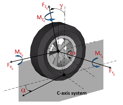
- Tydex-C Axis System
-
The “C” is for wheel center, and the C axis system has the following properties:
- The origin of the C-axis system is the wheel center.
- The X axis lies in the wheel plane and is parallel to the ground plane and points in the forward direction.
- The Y axis is perpendicular to the wheel plane and points towards the vehicle’s left side so that a positive rotation of the wheel and tire about the Y axis rolls the tire forward.
- The Z axis lies in the wheel plane, differs from vertical by inclination angle, and is perpendicular to the X and Y axis (Z= X x Y).

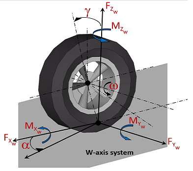
Figure 2. - Tydex-W Axis System
- The “W” is for wheel. The Tydex W axis system considers the local slope of the road
where the tire contacts the road, rather than assuming the road is flat.
- The origin of the W axis system lies at the ideal contact point between the wheel plane and local road plane, which is the intersection of the Tydex C System Z axis with local road plane.
- The X axis points forward along the line of intersection between the wheel plane and the local road plane.
- The Z axis is parallel to the local road normal and hence perpendicular to the local road plane.
- The Y axis is the projection of the wheel spin axis (Tydex C-Axis System Y) into the local road plane. The Y axis is perpendicular to both the X and Z axis (Y = Z x X).

Figure 3. - SAE Axis System
-
- X is forward
- Y is to the right
- Z is down
Multi-Threading
| Tire-Model | Multi-Thread | Enabling Multi-Threading |
|---|---|---|
| CD Tire | YES |
The CDTire.ini file controls multi-threading for CDTire. To enable multithreading, set the maximum threads in the parallel block to a number greater than one. For example:
|
| F Tire | YES | Multi-threading is controlled by the environment variable
NUSOL_MT_TIRE.
NUSOL_MT_TIRE= 0 (Single Threaded execution) |
| MF-Tire/MF-SWIFT | NO | Not Applicable |
| User Tire | NO | Not Applicable |