Helical Spring
A spring model in a vehicle carries the vertical load in a suspension, keeps the tire in contact with the road, and absorbs energy from road irregularities that would otherwise be transmitted to the vehicle and passengers.
The Helical Spring is a force-displacement entity designed to represent a vehicle spring. The spring force is interpolated from the force-deflection table stored in a TeimOrbit format property file.
Parameters
- Install Method
- Determines the installation method for the Helical Spring. Available options are
‘Points’, ‘Length’ and ‘Force’.
The Helical Spring install methods are used to ensure the springs carry the proper loads at the input position of the suspension.
-
- Points
- The distance between Points 1 and 2 fixes the initial length of the spring and
hence its force. Any changes in the location of Points 1 and 2 affect the
spring’s length, initial force, and line of action. The initial length
(l0) of the Spring
is:
Figure 1. Points for install method 
This is the typical choice when the points are located at the center of the upper and lower spring seats as shown in the figure below.Figure 2. Points for install method in a vehicle suspension 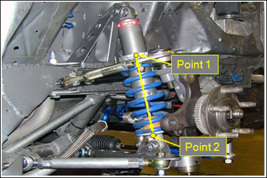
- Length
- Enter the length of the Helical Spring to fix its load. Altering the locations
of Points 1 and 2 changes the line the spring acts along, but not the springs
initial length and force.
Figure 3. Length for install method 
If a suspension employs the spring over the damper arrangement, the upper damper and lower damper points might be used to fix the line of action of the spring as shown in the figure below. However, the distance between these points is much greater than the length of the spring, therefore the spring force will not be correct. In such a case, use the Install Method as Length and enter the actual length of the spring. If the locations of Point 1 and Point 2 change, the initial spring length remains the value you entered.Figure 4. Length for install method in a vehicle suspension 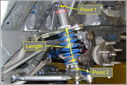
- Force
- Enter the initial force in the Helical Spring. Any changes in the locations of Points 1 and 2 only affect the Spring’s line of action. Further, changes to the spring properties like free length and stiffness do not affect the initial force. At initialization of the solver an iterative method is used to determine the Spring length that yields the entered force.
- Install Force/Length
- Option available for ‘Length’ or ‘Force’ Install Method selection. When Length option is selected, it specifies the installation length of the helical spring. When the Force option is selected, it determines the preload of the helical spring. With a given preload or installation length, MotionSolve determines the static spring force from the data in the helical spring property file.
- Property File
- The HelicalSpring properties are stored in a TeimOrbit format property file containing a table of the spring force versus spring displacement.
- Spring Length
- The length of the Helical Spring, corresponding to the distance between the mounting points. This parameter is not editable and is only used to demonstrate the current spring length before the simulation.
- Scale
- The scale options enable the scaling of the force and spring displacement without the need to directly modify the property file.
- Graphics
- Number of Coils and Coil Diameters parameters allow modified the graphic representing the helical spring for the visualization purpose.
Connecting an Helical Spring
-
From the guide bar, select the first body to
connect.
- Click Body 1 and select a
body from the modeling window.
OR
- Click the Body 1 Advanced Selector and select the required body from the dialog.
- Click Body 1 and select a
body from the modeling window.
- Similarly, select the second body to connect by clicking the Body 2 input collector.
-
Select a point and enter the location where the spring connects to Body
1.
- Click Point on Body 1 and select a point from the
modeling window.
OR
- Click the Point on Body 1 Advanced Selector and select the required point from the dialog.
- Click Point on Body 1 and select a point from the
modeling window.
-
Similarly, select the second point.
Typically, air springs act between the chassis and an axle. Point 1 on Body 1 defines the top of the air spring, while Point 2 on Body 2 defines the bottom of the air spring.
- Open the Helical Spring Entity Editor to edit the parameters.
Property File for Helical Spring
The Helical Spring properties are stored in a TeimOrbit format property file containing a table of the spring force vs spring displacement. When the model is submitted to the solver, MotionSolve reads the helical spring properties for use during the simulation. If the units specified in Helical Spring property file differ from the model, MotionSolve converts the spring properties to model units, however it leaves the property file unchanged.
The Helical Spring properties file contains header, units, spring data, and curve blocks. The units block specifies the length, mass, force, time and angle units employed in the file. The spring data block holds the spring free length. The curve block contains the table of displacement and force values.
Positive displacement in the spring is compression, while positive force acts to push apart the two bodies the spring connects. Thus, when plotted the force (Y) vs. displacement (X) curve should lie in the first and third quadrants.
$---------------------------------------------------------------------HEADER
[HEADER]
 FILE_TYPE           =  'spr'
 FILE_VERSION        =  4.0
 FILE_FORMAT         =  'ASCII'
$--------------------------------------------------------------------------UNITS
[UNITS]
 LENGTH        =  'mm'
 ANGLE         =  'degrees'
 FORCE         =  'newton'
 MASS          =  'kg'
 TIME          =  'second'
$--------------------------------------------------------------------SPRING_DATA
[SPRING_DATA]
 FREE_LENGTH  =  270.75
$--------------------------------------------------------------------------CURVE
[CURVE]
{  disp       force}
-300.0        -15000
-200.0        -12000
-150.0        -9000
-100          -6000
-50           -3000
-10           -600
0             0
10            600
50            3000
100           6000
150           9000
200           12000
300           15000
Subroutine Definition
Input Parameters
The Helical Spring subroutine is defined in the msautoutils.dll (.so) with sfosub function name.
Force subroutine input user string:
usrsub_param_str="USER(P1,P2,P3,P4,P5,P6,P7)"| Parameter | Description |
|---|---|
P1
|
Branch Flag = 1; ensures the helical spring force function |
P2 |
Helical Spring property file name solver string ID (.spr) |
P3 |
Force scale |
P4 |
Deflection scale |
P5 |
Installation method (0/3: length, 1: force, 2: points) |
P6 |
Installed value (preload or installed length) |
P7 |
Initial marker displacement |
Force Definition Block in the xml
<!-- MODEL.helicalspring_0.frcSpr -->
  <Force_Scalar_TwoBody
     id                  = "30301"
     label               = "HelicalSpring 0-spring"
     type                = "Force"
     i_marker_id         = "30302031"
     j_marker_id         = "30301011"
     usrsub_param_string = "USER(1,303001,1,1,2,0,500)"
     usrsub_dll_name     = "msautoutils"
     usrsub_fnc_name     = "sfosub"
  />
Outputs
| Type | Component | Quantity |
|---|---|---|
| User Defined (.plt) REQSUB (.abf) |
HelicalSpring – Spring output | Length |
| Rate of change of length | ||
| Spring force | ||
| Direction Cosine - X | ||
| Direction Cosine - Y | ||
| Direction Cosine - Z |
Output Subroutine Definition
The Helical Spring output subroutine is defined in the msautoutils.dll with FORCEREQ function name.
Output subroutine input user string:
usrsub_param_str="USER(P1,P2,P3)"| Parameter | Description |
|---|---|
| P1 | Branch Flag = 1 |
| P2 | Marker ID of body I |
| P3 | Marker ID of body J |
Output Definition Block in the xml
<!-- MODEL.helicalspring_0.o_userFrcSpring -->
  <Post_Request
     id                  = "70000000"
     label               = "HelicalSpring 0-Spring Output"
     comment             = "HelicalSpring 0-Spring Output"
     type                = "USERSUB"
     usrsub_param_string = "USER(1,30302031,30301011)"
     usrsub_dll_name     = "msautoutils"
     usrsub_fnc_name     = "FORCEREQ"
     cname2              = "Length"
     cname3              = "Rate of change of length"
     cname4              = "Spring force"
     cname6              = "DC-X"
     cname7              = "DC-Y"
     cname8              = "DC-Z"
  />