Bump Stop
The Bump Stop component limits suspension travel in bump (also known as jounce). When the distance between two bodies becomes small, the Bump Stop applies a force to push the bodies apart.
The Bump Stop force can be a linear or non-linear type and is computed from the force vs displacement table stored in a TeimOrbit format property file.
For a linear Bump Stop, the elastic force component is calculated using a third order polynomial, and for a non-linear Bump Stop the elastic force component is interpolated using the Akima method.
Parameters
- Property File
- The Bump Stop properties are stored in a TeimOrbit format property file containing a table of the force vs displacement.
- Install Method
- The install method is used to determine the distance at which the Bump Stop force
starts acting. There are two install methods available:
- Impact LengthThe impact length represents the distance between the Bump Stop attachment points when the impact happens.
Figure 1. Impact Length method 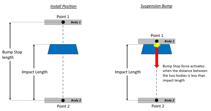
When the distance between the Body 1 and Body 2 is less than the impact length, the Bump Stop force acts. When the Impact Length install method is used, its value is directly used to activate the Bump Stop force between the two bodies.
- ClearanceUsing the clearance method, the Bump Stop force is activated when the distance between the Body 1 and Body 2 is less than the Bump Stop Length minus the Clearance value, that is, when the clearance reaches a value lower than zero.
Figure 2. Clearance method 
- Impact Length
- Install Distance
- The install distance represents the value of the selected install method. If Impact Length method is selected, the install distance value describes the impact length value. If the clearance method is selected, the install distance describes the clearance value.
- Bump Stop length
- The bump stop length is the distance between the Point 1 and Point 2 defined in the modeling configuration. This parameter is not editable and is only used to demonstrate the current bump stop length before the simulation.
- Scale
- The scale options enable the scaling of the force and displacement without the need to directly modify the property file.
- Graphics
- Two cylinder graphics represents the Bump Stop in MotionView. This parameter allows modify the Cylinder One and Cylinder Two radius for the visualization purpose.
Connecting a Bump Stop
-
From the guidebar, select the first body to connect.
- Click Body 1 and select a
body from the modeling window.
OR
- Click the Body 1 Advanced Selector and select the required body from the dialog.
- Click Body 1 and select a
body from the modeling window.
- Similarly, select the second body to connect by clicking the Body 2 input collector.
-
Select a point and enter the location where the spring connects to Body
1.
- Click Point on Body 1 and select a point from the
modeling window.
OR
- Click the Point on Body 1 Advanced Selector and select the required point from the dialog.
- Click Point on Body 1 and select a point from the
modeling window.
- Similarly, select the second point by clicking the Point 2 on Body 2 input collector.
- Open the Bump Stop Entity Editor to edit the parameters.
Property File
The Bump Stop properties are stored in a TeimOrbit format property file. When the model is submitted to the solver, MotionSolve reads the BumpStop property file for use during simulation. If the units in the property file differ from the model units, the solver internally converts the properties to the model units, however it leaves the property file unchanged.
The Bump Stop property file contains header, units, and curve blocks. The units block specifies the length, mass, force, time, and angle units employed in the file. The curve block holds a table of displacement against force values for the elastic force component.
$--------------------------------------------------------------------HEADER
[HEADER]
 FILE_TYPE     	=  'bum'
 FILE_VERSION  	=  4.0
 FILE_FORMAT   	=  'ASCII'
$---------------------------------------------------------------------UNITS
[UNITS]
LENGTH 	=  'mm'
ANGLE  	=  'degrees'
FORCE  	=  'newton'
MASS   	=  'kg'
TIME    	=  'second'
$---------------------------------------------------------------------CURVE
[CURVE]
{ disp    force}
 0.0   	0.0
 2.0   	1.0
 4.0   	2.0
 6.0   	3.0
 8.0   	4.0
10.0  	5.0
20.0  	6.0
30.0  	7.0
40.0  	8.0
50.0  	9.0
Subroutine Definition
Input Parameters
The Bump Stop subroutine is defined in the msautoutils.dll (.so) with sfosub function name.
Force subroutine input user string:
usrsub_param_str="USER(P1,P2,P3,P4,P5,P6,P7)"| Parameter | Description |
|---|---|
P1
|
Branch Flag = 3; ensures the bump stop force function |
P2 |
Bump Stop property file name solver string ID (.bum) |
P3 |
Force scale |
P4 |
Deflection scale |
P5 |
Bump Stop length |
P6 |
Install method (0: Clearance, 1: Impact length) |
P7 |
Install distance |
Force Definition Block in the xml
<!-- MODEL.bumpstop_0.frcBum -->
  <Force_Scalar_TwoBody
     id                  = "30301"
     label               = "Bumpstop 0-bumpstop"
     type                = "Force"
     i_marker_id         = "30302031"
     j_marker_id         = "30301012"
     usrsub_param_string = "USER(3,303001,1,1,500,0,0)"
     usrsub_dll_name     = "msautoutils"
     usrsub_fnc_name     = "sfosub"
  />
Outputs
| Type | Component | Quantity |
|---|---|---|
| User Defined (.plt) REQSUB (.abf) |
Bumpstop Output | Distance between points |
| Rate of change of displacement | ||
| Bump Stop Force | ||
| Direction Cosine - X | ||
| Direction Cosine - Y | ||
| Direction Cosine - Z |
Output Subroutine Definition
The Bump Stop output subroutine is defined in the msautoutils.dll with FORCEREQ function name.
Output subroutine input user string:
usrsub_param_str="USER(P1,P2,P3)"| Parameter | Description |
|---|---|
| P1 | Branch Flag = 1 |
| P2 | Marker ID of body I |
| P3 | Marker ID of body J |
Output Definition Block in the xml
<!-- MODEL.bumpstop_0.o_userFrcBumpstop -->
  <Post_Request
     id                  = "70000000"
     label               = "Bumpstop 0-Bumpstop output"
     comment             = "Bumpstop 0-Bumpstop output"
     type                = "USERSUB"
     usrsub_param_string = "USER(1,30302031,30301012)"
     usrsub_dll_name     = "msautoutils"
     usrsub_fnc_name     = "FORCEREQ"
     cname2              = "Dist. between points"
     cname3              = "Rate of change of dist."
     cname4              = "Bump stop. force"
     cname6              = "Direction Cosine-X"
     cname7              = "Direction Cosine-Y"
     cname8              = "Direction Cosine-Z"
  />