Board Spacing
Analyze clearances between the contour of the array board and the sub-boards.
Ensure the array board has enough clearance to the sub-boards and the objects on the sub-boards. Analyze one or both sides of a specified board.
The Board Spacing dialog contains the following
sections:
- Board Direction Definition: Decide the board's placement status using the
soldering mark or by defining the soldering direction.
- Soldering-Mark Component Group: Define the soldering mark. Use if it is registered as a group of components.
- Mark Direction: Define the mark’s direction and the soldering
direction.
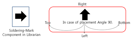
Figure 1. - Soldering Direction: Define the direction of the board without using
soldering-mark case.
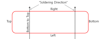
Figure 2.
- Component Clearance
- Item: Specify the item name.
- Component Group: Set the target components from the component group list.
- Layer: Select the target components layer.
- Placement Direction: Set the component placement status by considering the SMT process direction.
- Left of Board: Set the clearance value between the component and the left side of the board outline.
- Right of Board: Set the clearance value between the component and the right side of the board outline.
- Top of Board: Set the clearance value between the component and the top side of the board outline.
- Bottom of Board: Set the clearance value between the component and the bottom side of the board outline.
- Exceptional Component: Set the void-checking component group.
- Test Point Clearance
- TP Component Group: Select the test points component group from the group list.
- TP Pad Size Ranges: Set the ranges of the specified test-points pad size using the Floating Value Range Input tool.
- Top/Bottom Side Clearance
- Left of Board: Set the clearance value between the test point and the left side of the board outline.
- Right of Board: Set the clearance value between the test point and the right side of the board outline.
- Top of Board: Set the clearance value between the test point and the top side of the board outline.
- Bottom of Board: Set the clearance value between the test point and the bottom side of the board outline.
- Via Clearance
- Left of Board: Set the clearance value between the via and the left side of the board outline.
- Right of Board: Set the clearance value between the via and the right side of the board outline.
- Top of Board: Set the clearance value between the via and the top side of the board outline.
- Bottom of Board: Set the clearance value between the via and the bottom side of the board outline.