Manufacturing Check
Manufacturing check detects issues on sheet metal CAD parts.
- Nut bolt seating surface check
- Stud seating surface check
- Electrode interference check
- Spot weld surface area check
- Spot weld pitch check
- Spot gun interference check
- Arc weld torch interference check
- Fillet radius check
- Trim line radius check
- Hole pitch check
- Hole size check
- Hole size of nut bolt check
- Corner radius of oblong designed hole check
- Distance trim line hole end check
- Part interference check
The detected issues are summarized in a PowerPoint file.
-
From the Assembly ribbon, click the Verification
tool.
Figure 1. 
-
From the Verification Browser, right-click and select from the context menu.
The Manufacturing dialog opens.
Figure 2. 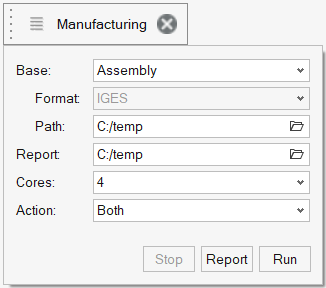
-
Define the following categories:
Option Definition Base Select the CAD data type. - XML (PLMXML or UDMXML)
- Assembly (CAD assembly files: UG Assembly, CATProduct, JT Assembly, and so on)
- CAD (refer to Config/CAD files)
- Multiple Assembly (multiple CAD assembly files)
Format The respective sub-data format is listed. Select the appropriate type. Path Use the file browser to navigate to the model you want to import. The selected location must contain the spot weld file. The spot weld file type must be set in the configuration file.Figure 3. 
Report Navigate to the directory where the generated reports will be saved. Cores Once activated, use the drop-down to select the number of cores for parallel processing. By default, the list box displays the number of processes minus 1. Action Choose between Check, Report, or Both. - Check performs only the comparison without the report generation.
- Report generates only the reports (Check performed previously).
- Both performs the comparison report generation sequentially.
Run Performs the function. Stop Stops the operation. -
Once the check has been completed, the Report button is
activated. Click Report to display the Summary PowerPoint
report or report location.
Figure 4. PowerPoint Summary (saved in the Report path) 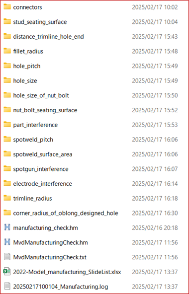
Each report folder has reports for each issue. The center image displays the model in 3D. Double click the image to rotate and zoom in.Figure 5. Detailed PowerPoint Report (stored in the Report path) 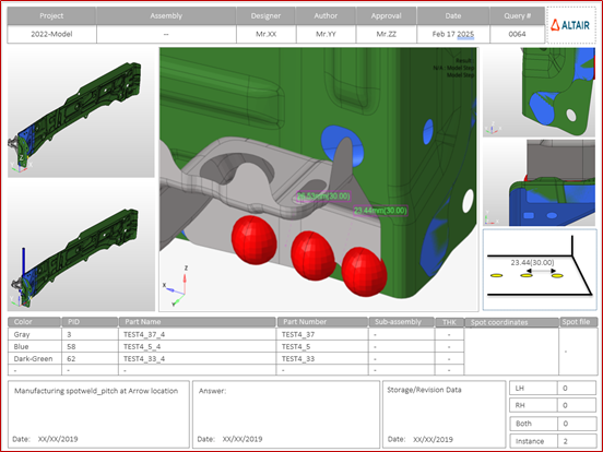
Output
Overview of the PowerPoint report generated from the Manufacturing check.
The PowerPoint report is separated into the following sections.
- Report Header
- Project name, assembly name, and slide number.
- Full Assembly Picture
- Image of the components that have connection issues.
- H3D Image
- This section can be viewed in HyperView Player. The H3D image displays the FE model with the connections marked with cross hairs.
- Issue Details
- Details of the components that have connection issues.
- User Review Section
- Add additional information when exchanging information with designers or engineers.
- Additional Information
- Occurrences of the issue are shown in the current slide. The number of instances indicate the number of occurrences of the issue.
Supported Manufacturing Checks
Most of the checks are performed on sheet metal parts. To perform most of the checks, the model is provided with thickness, while the material grade is provided through the CSV file.
- Nut bolt seating surface check
- Detects the holes in the model which do not have connectors around
them.
Figure 6. 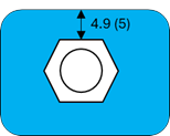
- Stud seating surface check
- Detects the bolts and nuts which do not have corresponding holes to fit
in.
Figure 7. 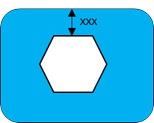
- Electrode interference check
- Detects the bolts which have a hole around it, but the distance between
the bolt center and hole center is more than the threshold value.
Figure 8. 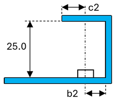
- Spot weld surface area check
- Detects the nuts which have a hole around it, but the distance between
the nut center and the hole center is over the threshold.
Figure 9. 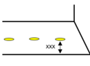
- Spot weld pitch check
- Based on the plate material, it checks the distance between weld
locations. The required distance is calculated based on the CSV file
table.
Figure 10. 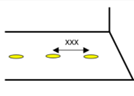
- Spot gun interference check
- Collision check between the spot gun and the weldable assembly
model.
Figure 11. 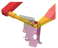
- Arc weld torch interference check
- Collision check between the arc torch, the weldable nut, and the
assembly model.
Figure 12. 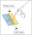
- Fillet radius check
- Checks the fillet radius against the material grade.
Figure 13. 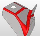
- Trim line radius check
- Checks the edge fillet radius values against the user-defined value.
Figure 14. 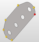
- Hole pitch check
- Checks the distance between the nearest holes against the threshold
value from the CSV file.
Figure 15. 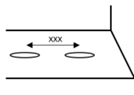
- Hole size check
- Checks the distance between the nearest holes against the threshold
value set in the CSV table.
Figure 16. 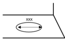
- Hole size of nut bolt check
- Checks the distance between the nearest holes. If it less than the
threshold, then reports are generated.
Figure 17. 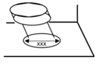
- Corner radius of oblong designed hole check
- Checks the radius of the oblong holes at the corners against the
threshold value in the configuration file.
Figure 18. 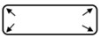
- Distance trim line hole end check
- Checks the distance between the hole edge against the nearest surface
edge, and compares the result with the CSV table.
Figure 19. 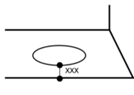
- Part interference check
- Checks the gap between the nearest parts at the physical location
without surface offset. You can perform a surface offset to check at the
mid location.
Figure 20. 