Visibility
![]()
Introduction
This tool is primarily used to display or hide objects in the User interface.
Options
| Option | Description |
|---|---|
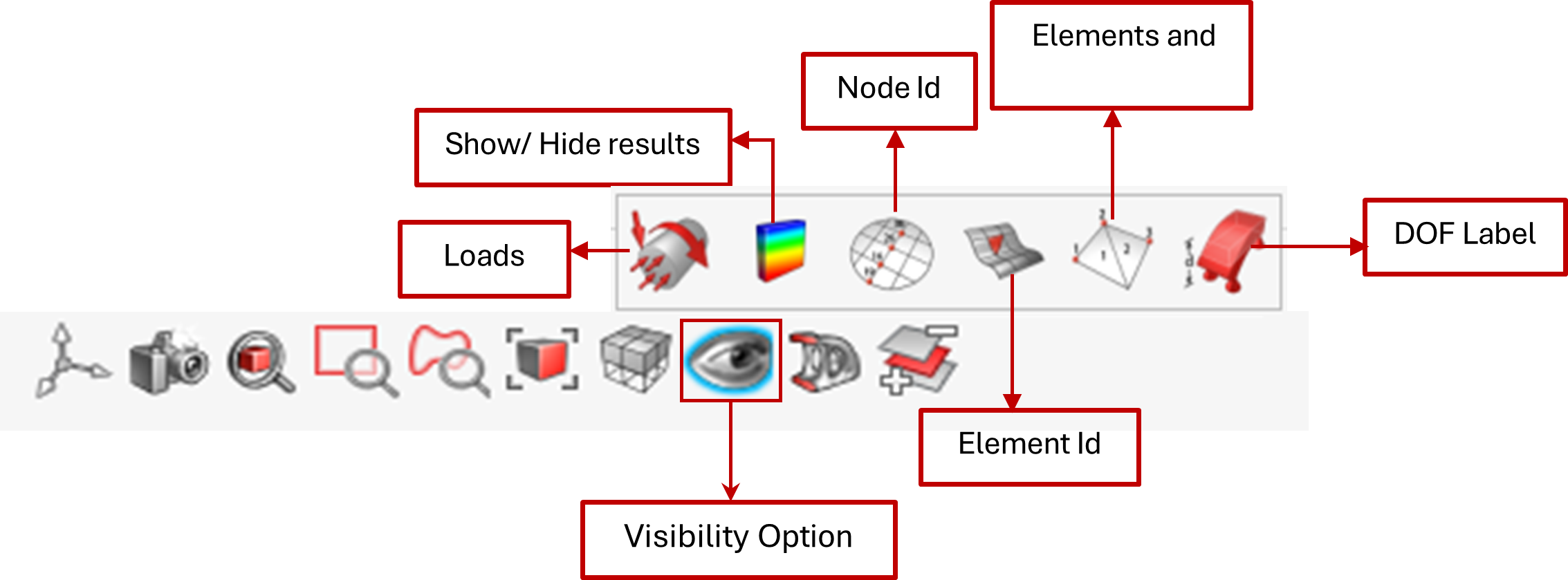
| Load | By default, this toggle is set to ON, displaying the entire load marker in the user interface. |
| Results | Turning ON this option enables result visibility, allowing you to toggle between showing and hiding the results. |
| Nodes | The IDs of the selected nodes will be displayed. |
| Elements | The IDs of the selected Element will be displayed. |
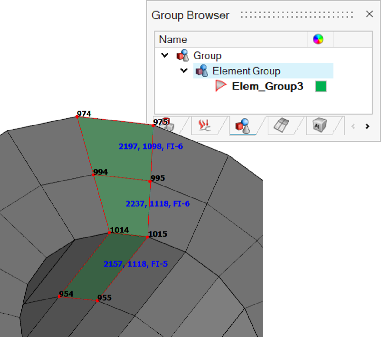
| Nodes and Elements | The IDs of the selected elements and their corresponding node IDs will be displayed. For solid elements, it will show the surface element ID, solid element ID, and the face index. |
| DOF label | This option shows the displacement and rotation values (Degrees of Freedom) for both fixed and enforced constraints. |
Note:
Node/element ID will can also be displayed in group display mode.
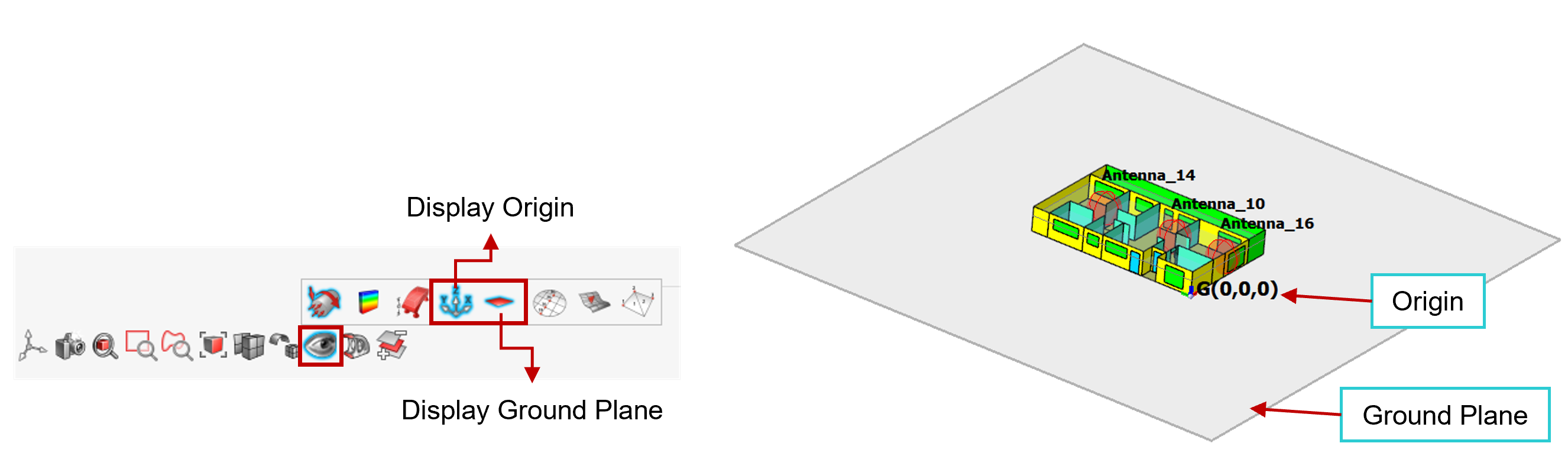
Display Options: Origin and Ground Plane
To improve the visualization of radio coverage setup modelling in the WinProp solution, two new display options have been added:
- Display Origin
Allows users to show or hide the solution origin coordinates. This feature helps identify the reference point used in simulations and can be toggled ON or OFF as needed.
- Display Ground Plane
Enables users to toggle the visibility of the ground plane in the GUI.
Note: This option will only be enabled if “WinProp solution” is
present.