Port

Introduction
Port load allows you to define where are located the physical pins for the connection of the electric and electronic components and, as a consequence, to indicate which are the input/output terminals to use for the definition of the S-parameters or Impedances to compute..
Two types of Port load are available: Differential and Single-Ended, which cannot co-exist, from a theoretical point-of-view, in a same simulation project. The Differential type requires in fact two input/output terminals for its definition, while for the Single-Ended the second terminal is naturally grounded.
For S-parameter computation, the use of Differential Ports allows to reduce the computation time, since the parasitics behavior of the interconnect is compacted in a smaller S-parameter matrix, but it requires more attention in the definition of the port terminals, in case the user wants to integrate the obtained S-matrices into circuit solvers. In case of Impedance computation, it is the only compatible ports type. Conversely, using Single-Ended Ports is more straightforward in that situation and also enables the generation of SPICE equivalent netlist, useful if the circuit solver is not able to read S-parameter Touchstone format. This ports type is not compatible with Impedance computation.
In this PE workflow, to create a port, the solution must be associated with meshed bodies, because the input/output terminals of the ports are identified by meshed faces.
Port definition dialog box
The choice between Differential and Single-Ended ports is made in the Create Solution dialog box, for S-parameter computation. For Impedance computation, only Differential type is available. For more details on the creation of the Parasitics Extraction solution, please refer to Parasitics Extraction solution.
The port definition dialog box is different between Differential Port and Single-Ended Port. Additionnaly, Differential Port dialog box is different between S-Parameter or Impedance computation.
| Differential Port | Single-Ended Port | |
|---|---|---|
| S-Parameter computation |
 |
 |
| Impedance computation | 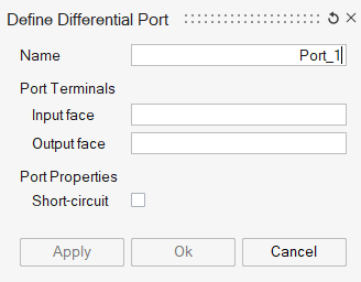 |
Not available |
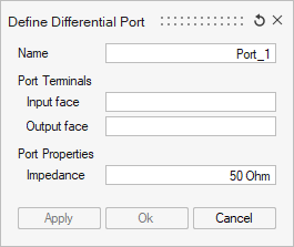
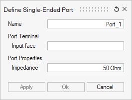
- the Name: by default, a name is suggested with an automated numbered index. Changing the index number does not affect the order of the ports in the Touchstone or SPICE exports, being the creation order considered for such purpose (as shown in the Loads and Constraints tree).
- the Port Terminals, identified by the input/output
faces where they are located.
- For the Differential port type, two terminals have to be defined geometrically by selecting an Input face and an Output face.
- For the Single-Ended port type, one terminal (identified by the Input face) is sufficient, as discussed in the Introduction here above.
Note: The selection of "Input face" or "Output face" could be one face, multiple faces, or a Face Group. This group can be created using the functionality Create Group.If a group of faces has been selected as Input/Output, it is not possible to select one of its faces alone as the port's Input/Output.
- the Port Properties:
- For S-parameter computation, the Impedance reference value to define the S-parameter of this port has to be defined. The 50 Ohm value typically used in most applications is proposed by default.
- For Impedance computation case, short circuit configuration can be considered, in which the two faces of the port are connected without any intervening resistance. However, it's important to note that when a port is short-circuited in this manner, it becomes impossible to calculate the impedance for that particular port. The short circuit option is used to establish a closed loop and facilitate the computation of loop impedance.