Surface Mesh - 3D Magnetic Solutions
![]()
Introduction
The Surface Mesh allows you to mesh all the faces of the device i.e. to generate the surface mesh.
Dialog Box

In the case of 3D Magnetostatic, 3D Transient Magnetic, and 3D AC Magnetic solutions:
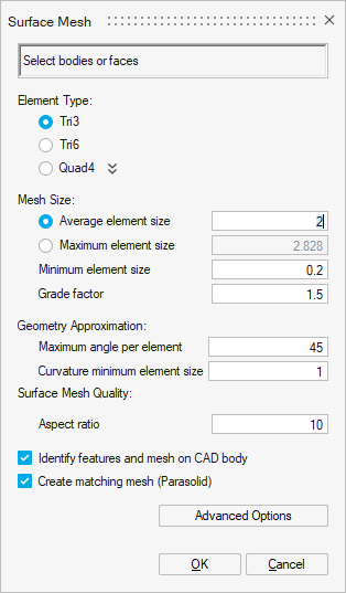
- The Element TypeAs part of the MS3D Workflow, MT3D Workflow, and MAC3D Workflow, it is recommended to use:
- Tri3 corresponding to 1st order triangular mesh elements
or- Tri6 corresponding to 2nd
order triangular mesh elements.
The 2nd order elements are necessary if there are solid conductors and if the Solver Settings Solving mode with Solid Conductor is set to Accurate (it is the default value). But please note that 2nd order mesh can lead to huge solving time increase in 3D.
Important: It is mandatory to have the same mesh order on all the bodies of the solution (Mesh Controls, Surface Mesh and Tet Mesh): all should be either of 1st order mesh only or all should be of 2nd order mesh only. - The Mesh Size
For example by entering the Average element size.
And it is mandatory to have a conforming surface mesh, so the Create matching mesh (Parasolid) option is checked by default.
Steps
- Click on the Surface Mesh button in
Mesh ribbon:

- For example, in our contactor project, we choose a 1st order mesh
(since we chose 1st order mesh elements for Mesh
Controls) with triangular elements:
In Element Type, check Tri3.
- In Mesh Size, in the Average element
size field, enter 2 mm.Important: Information you set in Mesh Controls has priority over what you set in Surface Mesh.
As a reminder, we set a mesh size of 0.5 mm on the 2 coil bodies.
Therefore, all the bodies except the ones corresponding to the 2 coils are meshed with an element size four times as large as on the coils.
- By default, if the solution is a 3D Magnetostatic or 3D Transient Magnetic
or 3D AC Magnetic one, the Create matching mesh
(Parasolid) option is checked, you can verify it.
 Important: The Create matching mesh (Parasolid) option must be checked in order to have a conforming surface mesh.
 - Select all the bodies:
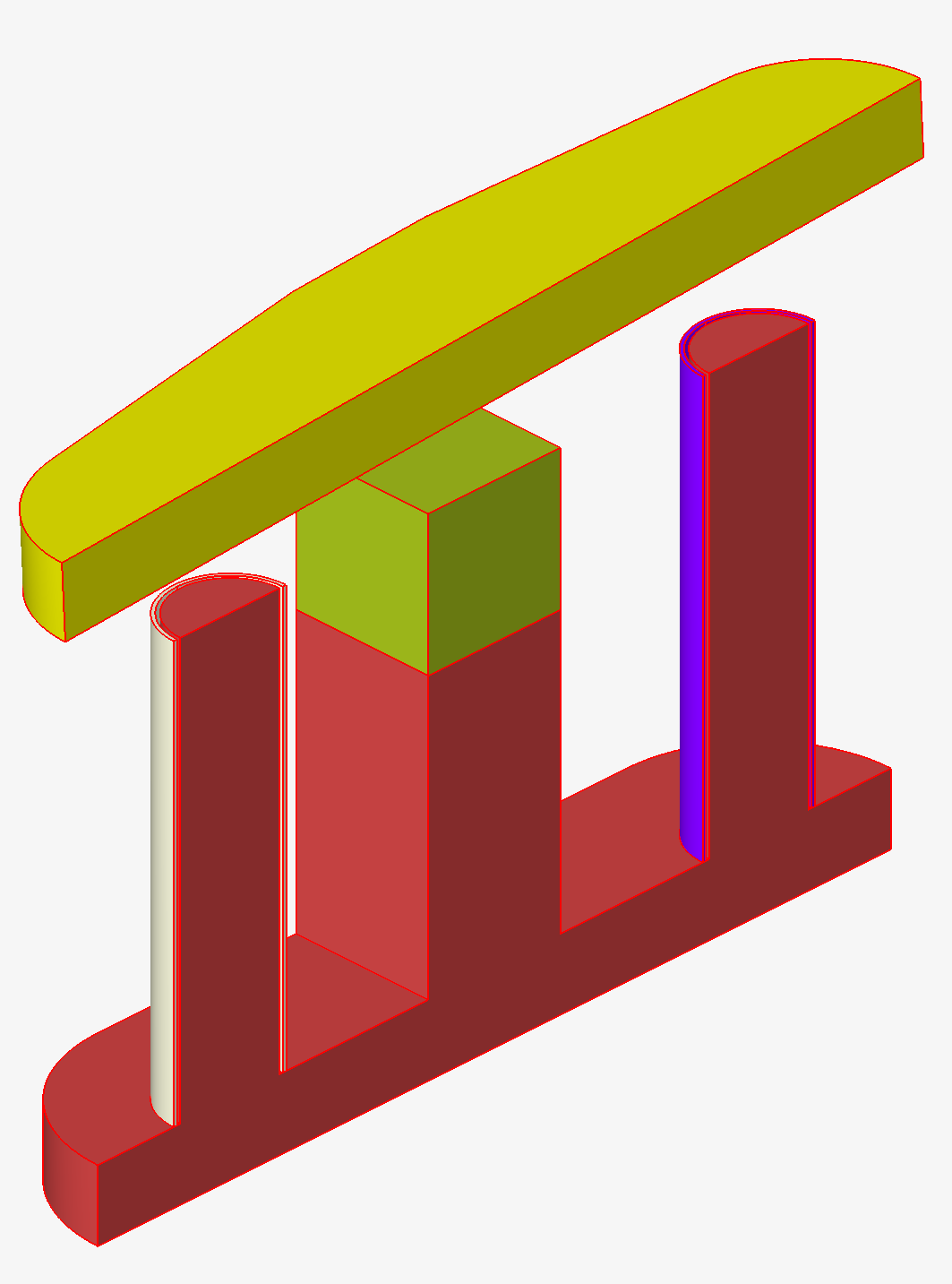
The outlines of all the bodies are displayed in red.
- Click on the OK button.
- Before generating the surface mesh, a warning window opens, as a conforming
surface mesh is going to be generated.
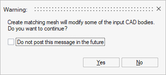
Click on the Yes button.
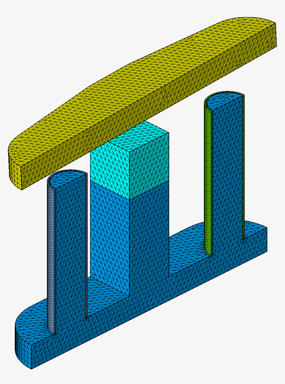
The surface mesh is generated.
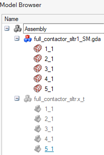
 To the left of the graphic window, in the Model Browser, in the 1st tab Assembly, there are the initial model .x_t and a new model .gda which has been created.
- The initial model .x_t corresponds to the CAD model and the corresponding bodies are now invisible.
- The new model .gda contains the meshed bodies and all are visible. The body icon corresponds to a surface mesh.
Before Surface Mesh After Surface Mesh 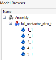
Advices
- After having optionally created and assigned Mesh
Controls on particular areas requiring a specific mesh, you
can generate the surface mesh on all the bodies via Surface
Mesh then generate the volume mesh via Tet
Mesh.
It is to be noted that all the mesh information set in Mesh Controls has priority over the information in Surface Mesh.
- Have the same mesh order on all the bodies of the solution is mandatory:
1st order mesh only or 2nd order mesh only.For example, for Surface Mesh:
- 1st order mesh with triangular elements: Tri3, for better meshing and solving performance
- 2nd order mesh with triangular elements: Tri6, necessary if there are solid conductors and if the Solver Settings Solving mode with Solid Conductor is set to Accurate (it is the default value)
- Generate a conforming surface mesh is mandatory, so the Create matching mesh (Parasolid) option must be checked, and if it is a 3D Magnetostatic or 3D Transient Magnetic or 3D AC Magnetic solution, this option is checked by default.
Limitations
Currently it is not possible to have quadrangular 2nd order surface elements on the solution bodies external faces. In fact, the infinite box cannot be created.