Electronics Thermal
![]()
Introduction
Check Solution link to learn about features of Solutions. Use SimLab - Learning center videos for more tutorials on Model setup using Solution approach.CFD Mode is supported for Electronic thermal management solution, it displays the entities on which boundary conditions are applied in colors.
Altair SimLab Electronics Thermal ( ElectroFlo) is a package designed to provide a solution for electronics thermal management in any electronics application.. ElectroFlo is a coupled thermal and CFD-based solution for problems involving conduction, natural and forced convection, radiation, and conjugate heat transfer, yet it is easy enough to use for a non-CFD expert.
The passage of electrical current in various traces and components results in generation of heat within these traces and component junctions (also known as component power dissipation or component losses). As a result of this heat generation, the component junction temperature will continue to rise until, in steady-state operation, it stabilizes at a point where heat transfer away from the component junction equals the component power dissipation. The most important factor in controlling the component junction temperature is the effectiveness of available heat flow paths. If the heat flow path is poor, the component temperature will rise beyond its safe limits, resulting in component failure or poor reliability.
In an electronic system, all modes of heat transfer (conduction, convection and radiation) are present and contributing to the heat transfer process simultaneously. The heat generated in a component junction is conducted to its external surfaces; the effectiveness of this conduction path is captured in component’s junction-to-case thermal resistance (Rjc). Higher values of Rjc will result in higher temperature rise from the component case to its junction. The component junction-to-case thermal resistance and the component maximum allowable temperature depend on the package construction details. These values can be obtained from the component manufacturer, usually available in component specifications.
A relatively small portion of the component losses are transferred directly from its external surfaces by convection to the internal ambient and radiation to its surroundings. Most of the component power dissipation is conducted to and spread within the board. The heat spreading can be greatly enhanced by the existence of full copper plane layers underneath the component and can be further improved by using thermal vias to efficiently conduct heat to these layers. The heat conducted to the board will in turn raise the board temperature which will initiate:
- Convection heat transfer to the internal cooling air
- Thermal radiation from the board and chassis to the surroundings. This is significant in loss-of-cooling operations mode.
- Conduction to the chassis through wedgelocks and stand-offs.
The strength of the software comes from its “hybrid” approach coupling various technologies and solution methods. Altair ElectroFlo provides an environment that offers a variety of approaches each ideal for modeling a specific aspect of the electronics thermal. The unique set of capabilities that Altair ElectroFlo offers are aimed at increasing accuracy while reducing modeling and simulation time.
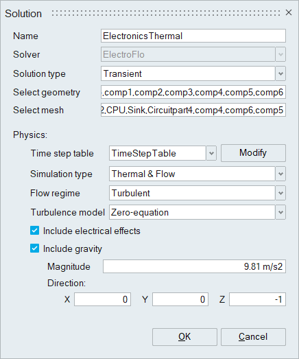
Analysis list of Electronics Thermal Solution
- Thermal and Flow: Navier-Stokes equations are solved
(coupled with the Energy Equation). CFD calculations can be
laminar or turbulent. Below turbulence models are supported for
Air.
- Zero-Equation model
- K-Epsilon model
- Spalart–Allmaras model
- Thermal: Only the energy equation is solved.Thermal mode will require application of convection heat transfer coefficient on all surfaces exposed to air, as energy equation is not solved in the air region.
- Flow: only Navier-Stokes equations are solved. The CFD solution can be used as a restart in a Thermal and Frozen Flow simulation to analyze one (or more) thermal scenarios where CFD has fully reached steady-state.
In all simulation modes (except for Flow), Joule heating contributions (trace heating and busbar heating) can be included by activating Electrical Co-Simulation (Coupled Electrical Solution).
Features
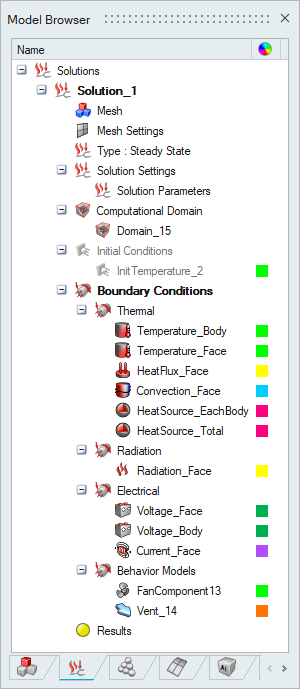
- The solution tree is listed with the proper grouping of the
boundary conditions. User can show or hide the boundary
conditions based on the grouping.
- Plot Convergence and View Log file options are supported in Results right click to track and review the Solutions.
- Kill Solving feature is supported in Results right click to terminate the solving process.
- Interact solver feature is supported in Results right click
to interact with the solver while solving the solution.
- Generate Files feature is supported to get the result and restart files from the solver after solving the current iteration
- Stop Solving feature is supported to terminate the solver after solving the current iteration and load the results in the solution
- Restart & Update feature is supported to restart the solution with reference to the restart file pointed. User has to select the restart(.rst) file as an input. Solver will start solving the solution from the restart file, instead of first iteration. while saving the database, the restart file also saved with the database in the same location.
- Thermal Convergence of the solution can be controlled by average temperature output from the sensor. User can turn ON the "Control thermal convergence with sensor" and select the sensor in "Select sensor to control convergence" in the solver settings to control the convergence.