Vibration Fatigue
![]()
Description
This tool is to determine the life of the electronic components connected to printed circuit board (PCB) using Steinberg’s fatigue life equation and Normal mode analysis result.
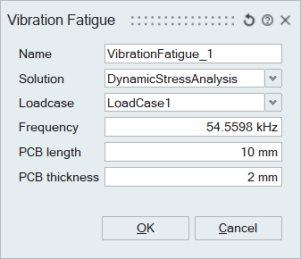
Inputs for tool are the following.
- Normal mode result.
- Component length.
- PCB length and thickness.
Method:
Once the solution is defined, we should define the following boundary conditions,
- Loading Data
- Component parameters
The relative displacement based on the Steinberg model and the normal mode result is calculated. With that ratio, the fatigue life of the component is computed.
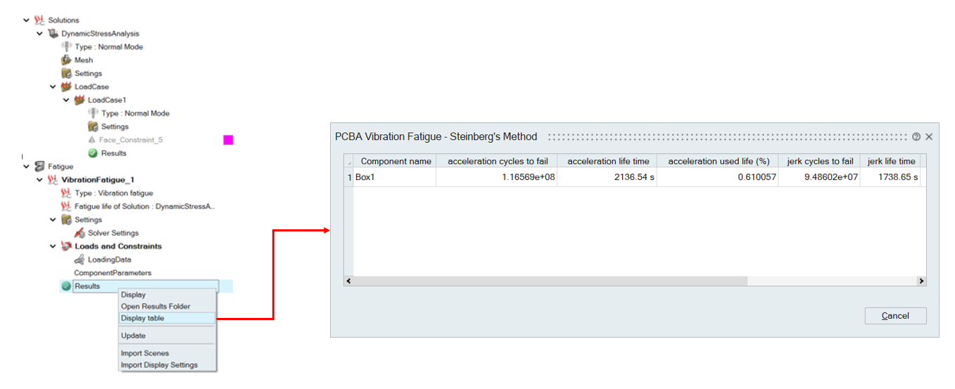
Once the solution is completed, the results can be viewed in a tabular format using the Display Table option available via right-click. The table also supports sorting for easier analysis.
Note:
- To compute life, the normal mode result should be displayed first.
- Reference:
- Andrés Garcíaa, Félix Sorribes-Palmerb, and Gustavo Alonsoc, “Application of Steinberg vibration fatigue model for structural verification of space instruments”, 2018. https://doi.org/10.1063/1.5019088
- Tom Irvine, “SHOCK and VIBRATION FATIGUE CRITERIA FOR ELECTRICAL COMPONENTS”, 2013.