Injection Molding
![]()
Note: Check Solution link to learn about features of Solutions. Use SimLab - Learning center videos for more tutorials on Model
setup using Solution approach.
List of Injection Molding Solution
- Fill
- Fill+Pack
- Fill+Pack+Cool
- Fill+Pack+Cool+Warp
- Fill+Cool
- Fill+Cool+Warp
- Cool
- Cool+Warp
Guidelines for Simulation
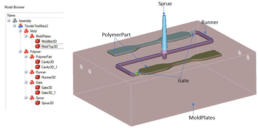
- CAD bodies or mesh bodies are used to create Molding solution.
- Part assembly should be correctly organized in Model Browser
- Polymer
- PolymerPart
- Sprue
- Runner
- Gate
- Mold
- MoldPlates
- MoldInsert
- PartInsert
In Molding application, user can select the body and classify bodies using below right click menu.
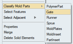
- Polymer
- For a model with multiple gates, different Injection_BC must be applied for every inlet. They should not be clubbed together.
- Before the deck can be exported, all BCs under loads and constraints should be applied correctly.
- Material and properties: Polymer material should be assigned for polymer bodies.
- CFD Mode is supported for the Molding solution, it displays the entities on which boundary conditions are applied in colors.
- SimLab supports the unit system, and it is recommended to set up molding problems using units. The solver uses SI units (m) for solving, and SimLab exports the solver deck in MKS (m kg N s) units.
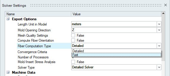
- Fast fiber orientation analysis:
- This option enables the computation of fast fiber orientation, and it is accomplished for a negligible incremental computational cost over the filling analysis. This analysis is supported only with the detailed solver. It cannot be used with the fast solver. In addition, the solver assumes the parameters for fiber-fiber orientation.
- The user can generate fast fiber orientation results if “Compute Fiber Orientation” is turned "ON" in the Solver Settings.
- To enable this feature, the user must select the "Fast" option in the
"Fiber Computation Type" from Solver Settings.
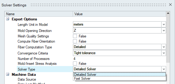
- Fast solver support:
- This option help to get a reliable quick solution in few minutes and it is available for Fill, Fill+Pack, Fill+Pack+Cool, Fill+Cool, and Cool analyses.
- The user has to generate a mesh that has only one element layer through the thickness for this solution type.
- To enable this option, user has to select "Fast Solver" in the "Solution
type" option from solution parameters.
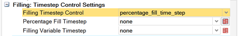
- Timestep control settings:
- These options are for advanced users. For normal usage, it is best to leave it to automatic time step control.
- These options help the user to specify time step control for the simulation.
- Separate timestep control is available for Filling, Packing, and Cooling Stages.
- Users can select the time step control type from “Filling Timestep Control” or “Packing Timestep Control” or “Cooling Timestep Control”.
- Then the user has to add the table values for the timestep by clicking on
the table button, corresponding to the time step type selected.
- CAD based Solution:
- AutoMesh tool can mesh the CAD bodies in the solution and update the mesh in the solution.
- Now the solution contains both Geometry and Mesh.
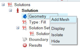
- If the AutoMesh is fails, user can manually mesh the bodies and include
those bodies into solution using "Geometry" right click "Add Mesh"
option.
- Following BCs can be applied on CAD bodies: Initial Condition, Injection BC, Vent and Convection.
- BCs like Contact, Symmetry, Valve Controller, Hot Runner and other node-based BCs can be applied only on meshed bodies.
- Click here for >CAD based Molding solution tutorial.
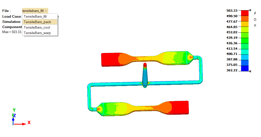
- Results: Multiple results file import supported for molding analysis. Based on the type of analysis, it will load the multiple files automatically when we attach results file.
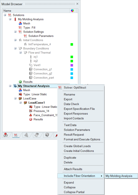
Fiber Orientation Mapping:
- Fiber orientation results can be generated in Molding, if the "Compute Fiber Orientation" options are turned ON in Molding solution parameters.
- User can map the fiber data to Linear / Non-Linear / Normal Mode Optistruct Solution. The results can be mapped to a part or entire model.
- Mapped data will be stored as a table in polymer material.
- In Polymer material, the user needs to select the MDS file from Material DB,
which has multiscale material information.
Polymer Material Data Validation:
- The molding interface now supports polymer material data validation on export. This feature will also create a PDF report of the material.
- If material data is incorrect, the export will be stopped and will alert the user.
- Users can refer to the files “Level0_check.txt” and “Level1_check.txt” in the export folder to understand the errors in material data.
Note: Check Injection Molding link for more
details.