Rigid Body
![]()
A rigid body is a solid body in which the deformation is zero or so small that it can be neglected. Mesh motion based on the dynamics of a rigid body is defined using the Rigid Body Motion panel.
Since the body is rigid, a detailed geometrical description of it is not necessary. Instead, only the modeled properties appearing as the coefficients in the dynamic translation and rotation equations need to be specified.
The rigid body is driven by the sum of two kinds of forces and moments. Internal refers to the integrated fluid traction and moment, and External to the force and moment specified by the user in this panel.
Description
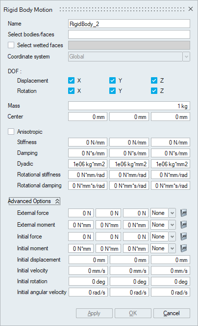
- Select Body
The bodies or faces to be modelled with Rigid Body Motion are specified using this option. The selected bodies/faces will be called as rigid body in this help section.
- Select Wetted faces
The faces to be modelled as wetted surface are specified using this option.
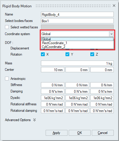
- Coordinate System
The available working coordinate system is selected using this option. If no new coordinate system is created by the user, then the Global coordinate system is selected by default and this option is frozen.
The new coordinate system is created using the Coordinate option under the Analysis Ribbon.
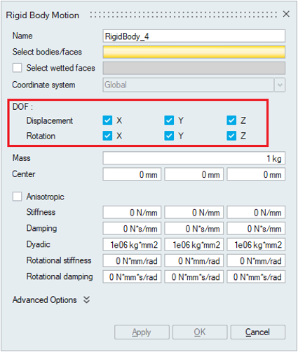
- DOF
Degrees of Freedom is used to specify constraints on the displacement and rotation of rigid body. The DOF consists of Translational constraints and Rotational constraints in the three available directions based on the working coordinate system. In this panel, the user has the ability to constraint the motion of the selected body or element set in any of six displayed options.
Checking the box here represents that the motion is not constrained in that direction.
The displacement option has three directions X, Y and Z. For example, in the below shown panel with all three directional boxes checked under displacement, the rigid body is allowed to translate in all the three directions. As the rotations are not checked, they are constrained in all three directions.
Depending on the application, the necessary DOF needs to be activated for the simulation. For example, if a rigid body is allowed to translate in X and Y direction and rotation around Z direction only, then X, Y next to Translation must be checked and Z in the Rotation row must be checked for rotation around Z axis.
- Mass
This option is used to specify the mass of the rigid body.
- Center
This option is used to specify the coordinate of the center of mass of the rigid body. When rigid body rotation is enabled (rigid body doing fixed-point rotation), the Center is regarded as the fixed rotation center, not necessarily center of mass.
- Anisotropic
Anisotropic can be enabled when the properties change in more directions in addition to X, Y, Z (orthotropic). When the anisotropic option is enabled, User can provide 6 components (X, Y, Z, XY, YZ, ZX) for each property. By default, this option is unchecked.
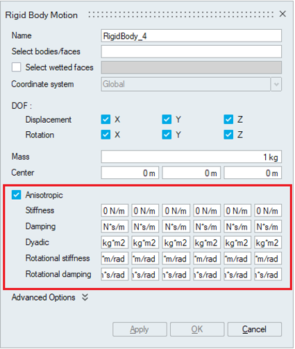
- Stiffness
The symmetric stiffness matrix for the translational rigid body is specified using this option. The corresponding values are defined in each direction.
- Damping
The symmetric damping matrix for the translational rigid body is specified using this option. The corresponding values are defined in each direction.
- Dyadic
The symmetric dyadic (moment of inertia) matrix for the rotational rigid body is specified using this option. The corresponding values are defined in each direction.
- Rotational stiffness
The symmetric rotational stiffness matrix for the rotational rigid body is specified using this option. The corresponding values are defined in each direction.
- Rotational damping
The symmetric rotational damping matrix for the rotational rigid body is specified using this option. The corresponding values are defined in each direction.
- Stiffness
- Advanced Options
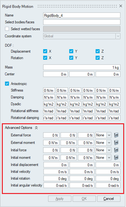
- External force
This is the external force vector on the rigid body specified in the defined coordinate system. The multiplier function is used to specify time varying external force values.
- External moment
This is the external moment vector on the rigid body specified in the defined coordinate system. The multiplier function is used to specify time varying external moment values.
- Initial force
This option is used to specify the initial internal force vector on the rigid body. The corresponding value is defined in each of the directions. The multiplier function is used to specify time varying initial force values.
- Initial moment
This is the initial internal moment vector on the rigid body specified in the defined coordinate system. The multiplier function is used to specify time varying initial moment values.
- Initial displacement
This option is used to specify the initial displacement values of the rigid body.
- Initial velocity
This option is used to specify the initial velocity values of the rigid body.
- Initial rotation
This option is used to specify the initial rotation values of the rigid body.
- Initial angular velocity
This option is used to specify the initial angular velocity values of the rigid body.
- External force