Outlet
![]()
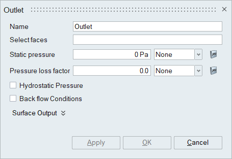
The outlet panel is used to define the outflow boundary condition for a fluid flow problem.
Description
- Select faces
The select faces option is used to select the faces to be assigned the outlet boundary condition. Outlet can be assigned on faces/face groups of volume meshed bodies.
- Static Pressure
The Static pressure is applied to the outlet face. The multiplier option is used to specify the time varying static pressure value.
- Pressure loss factor
The pressure loss factor is used to specify a coefficient of pressure loss that will be added to or subtracted from the pressure boundary condition. The multiplier option is used to specify the time varying pressure loss factor.
- Hydrostatic pressure
Hydrostatic pressure is the pressure that is exerted by a fluid at equilibrium at a given point within a fluid, due to the force of gravity. This option can be enabled to add the hydrostatic pressure term to the overall pressure boundary condition.
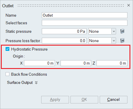
The coordinates of the origin of the body to which this flow boundary condition is assigned should be specified in the X, Y and Z options. You can also click on either X, Y, Z value location and select a node in the model for hydrostatic pressure origin.
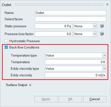
- Back flow conditions
The Back flow conditions must be enabled when there is some flow over a portion of an outflow where the velocity is into the fluid domain. This may lead to instability of the temperature, species, viscoelastic stress, kinetic energy, eddy frequency, and eddy viscosity variables. Enabling back_flow_conditions allows boundary conditions to be specified for these variables only on nodes where there is flow re-entering the domain.
A back flow type of value uses nodal boundary conditions specified by the temperature, species_1,..., species_9, viscoelastic_xx_stress, ..., viscoelastic_zx_stress, kinetic_energy, eddy_frequency, and eddy_viscosity parameters and their corresponding multiplier function parameters. Instead of specifying a value, various solution averages may be used. A back flow type of area_average averages the solution variable over the entire outflow surface and uses the result for the nodal boundary condition.
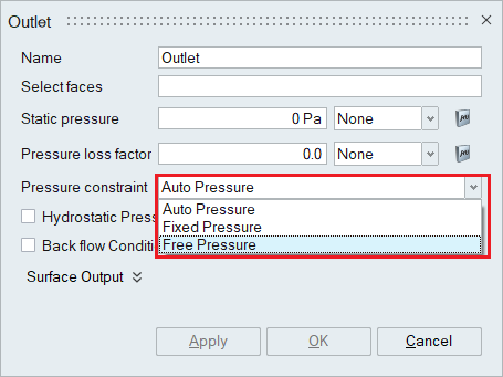
- Compressible Flow SimulationWhen the Compressible flow option is chosen in the Solutions panel, pressure constraint is enabled in outlet boundary condition panel.
- Auto Pressure - The user specified pressure is used in subsonic flow, while the user specified pressure is ignored if it is lower than the computed pressure on the outflow surface.
- Fixed Pressure - Pressure is specified by user.
- Free Pressure - The user specified pressure is ignored.
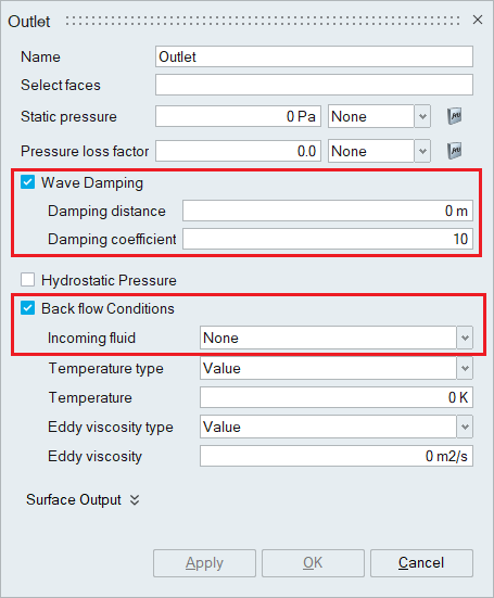
- Immiscible Multiphase Flow SimulationWhen the Multiphase flow option is enabled in the Solutions panel, Wave damping option will be enabled in the outlet boundary condition panel.This command is used to damp a surface wave in a multiphase flow problem by adding momentum source per unit volume to the momentum equation along the direction of gravity.
- Damping distance - Distance from the outlet surface where the damping source term is active.
- Damping coefficient - Coefficient multiplying the damping source term.
When the Multiphase flow option is enabled in the Solutions panel, the incoming fluid type should be mentioned in the outlet boundary condition panel when back flow condition is enabled.
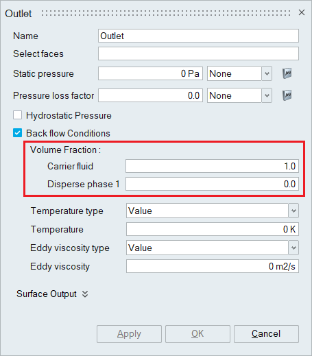
- Disperse / Eulerian Multiphase Flow Simulation
When the Disperse / Eulerian Multiphase flow type is chosen in the Solutions panel, the Volume fraction option becomes available in the outlet boundary condition panel when the backflow condition is enabled.
The volume fraction of the carrier fluid and the volume fraction of the Dispersed phase should be mentioned appropriately.
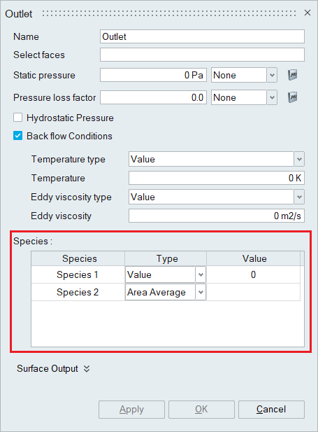
- Species
When the number of species is specified in the Solutions panel, the Species option becomes available in the outlet boundary condition panel when the backflow condition is enabled. The species value should be mentioned appropriately.
- Surface Output
Surface Output specifies the output parameters for a boundary face.
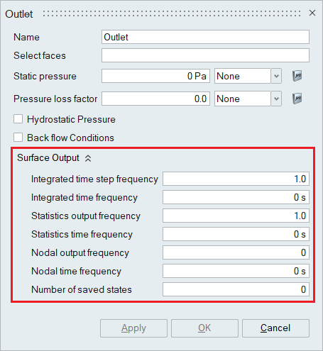
- Integrated output frequency
Time step frequency at which the integrated surface quantities are output. If zero, this option is ignored.
- Integrated output time interval
Time frequency at which the integrated surface quantities are output. If zero, this option is ignored.
- Statistics output frequency
Time step frequency at which the statistics of surface nodal quantities are output. If zero, this option is ignored.
- Statistics output time interval
Time frequency at which the statistics of surface nodal quantities are output. If zero, this option is ignored.
- Nodal output frequency
Time step frequency at which the surface quantities at the nodes of the surface are output. If zero, this option is ignored.
- Nodal output time interval
Time frequency at which the surface quantities at the nodes of the surface are output. If zero, this option is ignored.
- Number of saved states
Number of solution steps to retain on the disk. If zero, all the solution steps are retained.
- Integrated output frequency